Specifications for Pad Mounted Transformer for Wholesalers
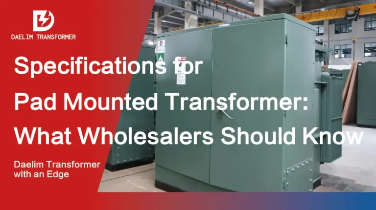
Wholesale transformer distributors need to address the increasing demand for pad-mounted transformers in renewable energy projects. As renewable energy systems like wind and solar farms become more widespread, outdated transformers often face issues such as overload, shorter operational lifespans, or failure due to fluctuating power demands. Pad-mounted transformers offer a modern solution for these challenges, allowing for reliable performance in both primary installations and as backup units.
Key Takeaways
- Pad-mounted transformers are essential in renewable energy systems, replacing outdated transformers that often face overload or shortened lifespans.
- Single-phase pad-mounted transformers are suitable for smaller renewable systems, with capacities up to 250 kVA and environmentally friendly insulation fluids like FR3™.
- Three-phase pad-mounted transformers are used in larger installations, with capacities ranging from 75 kVA to 10,000 kVA, and can handle fluctuating loads typical in renewable energy projects.
- Pad-mounted transformers offer improved durability and are ideal for both primary installations and as backup units in renewable energy systems.
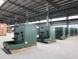
Skid Mounted Transformer(Small-substastion Transformer)
Single Phase Pole Mounted Transformer
Oil Immersed Power Transformer
Table of Content
Single Phase Pad Mounted Transformer for Renewable Energy
In renewable energy applications, single-phase pad-mounted transformers are commonly used for smaller, distributed systems. Their specifications include:
- Primary Voltage: 34.5kV-19.92kV, 24.94kV-14.4kV, or other renewable-compatible configurations.
- Secondary Voltage: 120-240V or 240-480V, ideal for localized energy distribution.
- Capacity: Up to 250 kVA, suitable for handling smaller energy flows from renewable sources.
- Durability: Enhanced with anticorrosion skirts, making them perfect for outdoor and exposed renewable energy environments.
- Insulation Fluids: Environmentally friendly options like FR3™ fluid are available to align with the sustainability goals of renewable energy projects.
The renewable energy market requires transformers that can handle frequent load fluctuations and overloads, which pad-mounted transformers are designed to support, ensuring that systems continue to operate smoothly despite high demand.
Key Specifications for Single Phase Pad Mounted Transformer
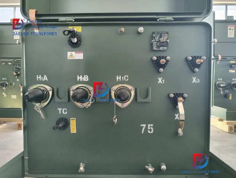
Single-phase pad-mounted transformers are widely used in distribution networks, including in renewable energy applications. These transformers are specifically designed for underground power distribution, offering a safe, reliable, and efficient method for stepping down high voltages to levels suitable for homes, small businesses, or renewable energy systems like solar and wind farms.
Get it now: What is a pad-mounted transformer?
Key Specifications for Single Phase Pad Mounted Transformer
Single-phase pad-mounted transformers are widely used in distribution networks, including in renewable energy applications. These transformers are specifically designed for underground power distribution, offering a safe, reliable, and efficient method for stepping down high voltages to levels suitable for homes, small businesses, or renewable energy systems like solar and wind farms.
Capacity
- Single-phase pad-mounted transformers typically have a capacity range of 15 kVA to 250 kVA. These transformers are ideal for residential or small-scale renewable energy applications, where power demand fluctuates but generally remains under 250 kVA.
Primary Voltage
- Primary voltage ratings are critical to ensure compatibility with upstream power systems. The primary voltage range for single-phase pad-mounted transformers typically includes:
- 34.5 kV – 19.92 kV
- 24.94 kV – 14.4 kV
- 13.8 kV – 7.957 kV
- 13.2 kV – 7.62 kV
- 12.47 kV – 7.2 kV These voltage ratings ensure that the transformer can handle high input voltages, converting them to a lower, usable voltage for downstream applications.
- Primary voltage ratings are critical to ensure compatibility with upstream power systems. The primary voltage range for single-phase pad-mounted transformers typically includes:
Secondary Voltage
- The secondary voltage is the output voltage after transformation. Common secondary voltage ratings include:
- 120-240V
- 240-480V
- 347/600V These voltages are ideal for delivering electricity to homes, small businesses, or distributed renewable energy installations.
- The secondary voltage is the output voltage after transformation. Common secondary voltage ratings include:
Insulation Fluids
- Single-phase pad-mounted transformers are equipped with insulation fluids to maintain temperature stability and prevent overheating. Two common types are:
- Mineral insulating oil: Traditional insulation fluid.
- Envirotemp™ FR3™ fluid: A fire-resistant, eco-friendly alternative that aligns well with renewable energy goals.
- Single-phase pad-mounted transformers are equipped with insulation fluids to maintain temperature stability and prevent overheating. Two common types are:
Cooling and Thermal Management
- These transformers often rely on natural air or oil cooling to dissipate heat. This helps to prevent overheating during high-demand periods, ensuring long-term reliability.
Overload Protection and Taps
- Single-phase pad-mounted transformers come with load-break switches and high-voltage taps that allow for adjustments to handle fluctuations in load. Taps usually offer a range of 2×2.5%, allowing for fine-tuning of the voltage output.
Build and Durability
- These transformers are built for outdoor installation with mild steel or stainless steel tanks, providing protection against weather conditions, corrosion, and contaminants. For high-contamination areas, an anticorrosion skirt is typically included.
- Transformers also come with features such as oil level sight gauges, drain plugs, and filler plugs to ensure maintenance can be easily performed.
- They meet or exceed standards like ANSI/IEEE C57.12.90, which governs safety and performance, including routine tests for voltage ratios, polarity, and load losses.
Electrical Specifications
- Impedance is designed to limit short-circuit current at service equipment. For example:
- 75 kVA: 2.0% impedance.
- 100–167 kVA: 2.5% impedance.
- Transformers are capable of withstanding impulse voltages according to standards such as ANSI/IEEE C57.12.35 and can handle fault currents in the range of 12 kA for 1 second, depending on the model.
- Impedance is designed to limit short-circuit current at service equipment. For example:
Operational Temperature
- Designed for a wide range of operating conditions, these transformers can function between -40°C to 120°C, making them suitable for various climates and environments.
Routine Testing
- Before shipment, transformers undergo rigorous testing, including:
- Ratio testing on each connection.
- Polarity testing to ensure correct electrical orientation.
- No-load loss testing at 105% of the rated voltage.
- Exciting current testing at 105% of rated voltage.
- Leak-detection testing for the transformer tank to ensure durability and safety.
- Before shipment, transformers undergo rigorous testing, including:
Get it now: Distribution Transformer Standards in Canada
Specifications for Single Phase Pad-Mounted Transformer
| Section | Detail | Specification |
| 1. General Specification | Rated Capacity | 15-250 kVA |
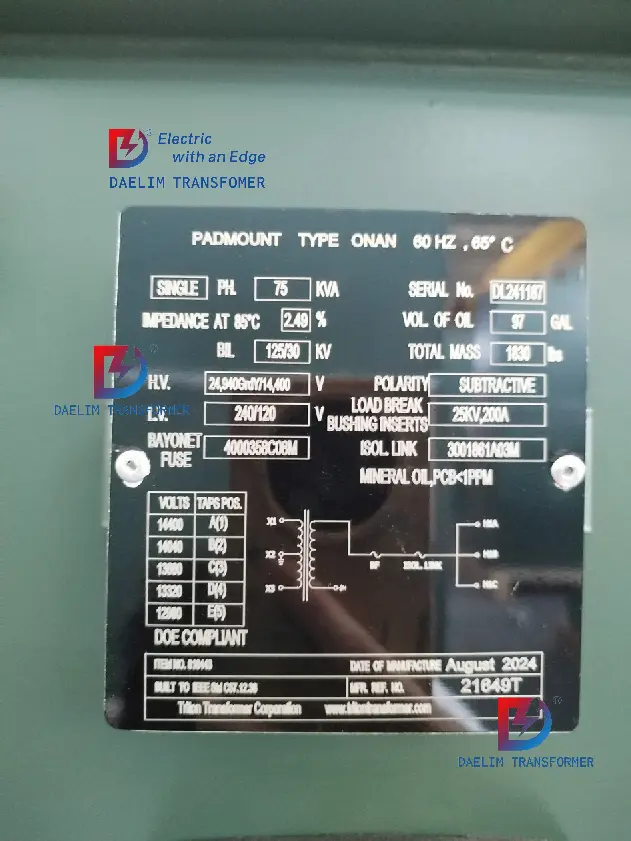
| Product Type | ZGDL-H-100/7.2 (0.24/10.12) | |
| Factory Serial No. | DL202090305 | |
| Voltage Combination | Primary: 34.5kV-19.92kV, 24.94kV-14.4kV, 13.8kV-7.957kV, 13.2kV-7.62kV, 12.47kV-7.2kV or others | |
| Secondary Voltage | 120-240V, 240-480V, 347-600V or others | |
| Frequency | 60 Hz | |
| Current | HV: 13.889 A / LV: 416.67 A | |
| Polarity | Il6 | |
| Standards | ANSI, IEEE, DOE, CSA, NEMA, UL/cUL, CSA listing | |
| Configuration | Loop or Radial Feed | |
| Insulation Fluids | Mineral Oil, Envirotemprm FR3TM | |
| Tank Material | Mild Steel (Optional Stainless Steel) | |
| Impulse Test Standard | ANSI/IEEE C57.12.90 | |
| Hot-stick operable | Yes | |
| 2. HV Tap Range | H.V. TAP Range | 2×2.5% or others |
| BIL (Basic Impulse Level) | 30V-150V, Rated 21.9 kV phase-to-ground, 150 kV BIL | |
| Short-Circuit Withstand Capability | 19.2 kA asymmetrical, 10 cycle per ANSI C37.72 | |
| Minimum Impedance | (i) 75 kV•A: 2.0%; (ii) 100–167 kV•A: 2.5% | |
| 3. Measurement of Voltage Ratio | Tapping Position 1 | HV: 7.56 / LV: – / HV/LV (%): 0.01 |
| Tapping Position 2 | HV: 7.38 / LV: – / HV/LV (%): 0.01 | |
| Tapping Position 3 | HV: 7.20 / LV: 0.24 / HV/LV (%): 0.01 | |
| Tapping Position 4 | HV: 7.02 / LV: – / HV/LV (%): 0.01 | |
| Tapping Position 5 | HV: 6.84 / LV: – / HV/LV (%): 0.01 | |
| 4. Measurement of Winding Resistance | Tapping Position 1 (Ω) | HV: 1.375 / LV: x1x2 (Ω): 0.001210 |
| Tapping Position 2 | HV: 1.342 / LV: x2x3 (Ω): 0.0007515 | |
| Tapping Position 3 | HV: 1.309 / LV: – | |
| Tapping Position 4 | HV: 1.276 / LV: – | |
| Tapping Position 5 | HV: 1.242 / LV: x1x3 (Ω): 0.001748 | |
| 5. Routine Test Items | Ratio on each connection | As per ANSI/IEEE requirements |
| Polarity | Verified | |
| No-load Loss (105% Rated Voltage, 85°C) | 199 W | |
| Exciting Current (105% Rated Voltage) | 0.25% | |
| Load Loss and Impedance at Rated Current | 750 W / Impedance 2.70% | |
| Applied Voltage | Verified | |
| Induced Voltage | Verified | |
| Transformer Tank Leak-Detection Test | Passed | |
| 6. Additional Features | Oil Level Sight Gauge | Ensures safe operation of load-break switches |
| Load-Break Switches | Load-break switch nameplate, padlocking provision | |
| High Voltage Taps | Yes | |
| Bushing Type | Stud-type or Spade-type Low-Voltage Bushings | |
| Corrosion Protection | Anticorrosion skirt for contaminated areas | |
| Operation Temperature Range | -40 °C to 120 °C | |
| Fire-Resistant Fluid | KNAN or LNAN available |
Advantages for Renewable Energy Systems
In the context of renewable energy, single-phase pad-mounted transformers offer several benefits:
- Eco-friendly Insulation: FR3™ fluid enhances safety and aligns with sustainability goals.
- High Efficiency: These transformers have low no-load losses, crucial for optimizing renewable energy systems where power may be intermittent.
- Durability: With features like corrosion resistance and thermal stability, these transformers are built to last even in challenging outdoor environments.
- Customizability: With adjustable taps and overload protection, these transformers can handle the variable output from renewable sources, preventing overload and premature failure.
By understanding these specifications for single-phase pad-mounted transformers, wholesalers and distributors can offer reliable, long-lasting products tailored to the growing renewable energy market, where transformer replacement and backup systems are essential to managing fluctuating loads and ensuring uninterrupted power distribution.
Get it now: Distribution Transformer Standards in Canada
How to Interpret Specifications for Single-Phase Pad-Mounted Transformers
General Specification
In this section, we are covering the basic details of the transformer, including its capacity, product type, voltage levels, and standards that it complies with.
Rated Capacity (15-250 kVA): This is the power rating of the transformer. It tells us the amount of electrical power the transformer can handle. For single-phase pad-mounted transformers, the typical range is from 15 kVA to 250 kVA, meaning they can manage electrical loads within this range.
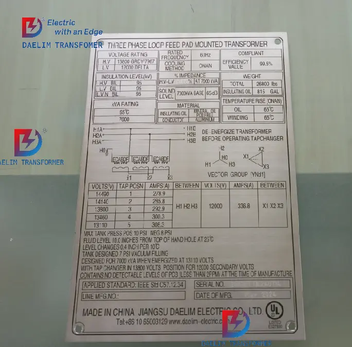
Product Type (ZGDL-H-100/7.2 (0.24/10.12)): This refers to the specific model of the transformer. The numbers here indicate the rated voltage and current configurations.
Factory Serial No. (DL202090305): This is a unique identification number assigned to the transformer for tracking and reference. It’s used for warranty, servicing, and manufacturing purposes.
Voltage Combination (Primary: 34.5kV-19.92kV, 24.94kV-14.4kV, etc.): This shows the different voltage combinations the transformer is designed to handle. The primary voltage refers to the high voltage the transformer receives, which can be as high as 34.5 kV (kilovolts). Several voltage configurations are available to match different applications.
Secondary Voltage (120-240V, 240-480V, etc.): The secondary voltage is the low voltage output from the transformer. It typically steps down the high voltage to these lower levels, making the electricity suitable for use in homes, commercial buildings, or small industrial setups.
Frequency (60 Hz): This refers to the frequency of the electrical current that the transformer is designed to work with. In most countries like the US, the frequency of the power grid is 60 Hz (Hertz).
Current (HV: 13.889 A / LV: 416.67 A): The current rating indicates the amount of electric current that flows through the transformer on the high-voltage (HV) and low-voltage (LV) sides. For example, the transformer can handle a high-voltage current of 13.889 amps and a low-voltage current of 416.67 amps.
Polarity (Il6): Polarity is important when connecting transformers to ensure the voltage relationships between the terminals are correct. The polarity here is marked as Il6, which is a specific configuration indicating how the transformer’s windings are connected.
Standards (ANSI, IEEE, DOE, CSA, NEMA, UL/cUL, CSA listing): These are the international standards that the transformer complies with. They ensure that the transformer meets industry requirements for safety, performance, and durability. ANSI (American National Standards Institute), IEEE (Institute of Electrical and Electronics Engineers), DOE (Department of Energy), and CSA (Canadian Standards Association) are common regulatory bodies, and NEMA (National Electrical Manufacturers Association) is a key industry group.
Configuration (Loop or Radial Feed): The transformer can be configured in two ways: a loop feed, which allows for multiple electrical paths (in case one fails, another can supply power), or a radial feed, which is a simpler configuration with one electrical path.
Insulation Fluids (Mineral Oil, Envirotemprm FR3TM): The transformer uses insulation fluids to cool and insulate its internal components. Mineral oil is the traditional choice, while Envirotemprm FR3TM is a biodegradable and environmentally friendly alternative.
Tank Material (Mild Steel or Optional Stainless Steel): The external tank of the transformer is made of either mild steel or stainless steel (optional). Stainless steel is more resistant to corrosion, making it ideal for harsh environments.
Get it now: What is a Skid Mounted Transformer?
HV Tap Range
HV taps are used to adjust the voltage in small increments to accommodate variations in the power supply, ensuring the transformer operates efficiently under different conditions.
Let’s break it down for readers in a table format for better clarity:
| Specification | Explanation |
|---|---|
| H.V. TAP Range (2×2.5% or others) | The HV tap range allows for voltage adjustments by increments of 2×2.5%. This means that the transformer can adjust its high voltage input to compensate for voltage variations. This feature helps maintain the correct output voltage under different power conditions. It is especially important in Specifications for Single-Phase Pad-Mounted Transformers used in various grid and industrial applications where voltage stability is crucial. |
| BIL (Basic Impulse Level: 30V-150V) | Basic Impulse Level (BIL) refers to the maximum voltage a transformer can withstand during a transient voltage spike, such as lightning or a switching surge. In this case, the transformer has a BIL rating of 30V-150V, ensuring it can handle voltage surges without sustaining damage. This is a critical specification for single-phase pad-mounted transformers, particularly in areas with frequent electrical disturbances. |
| Short-Circuit Withstand Capability | The transformer is designed to withstand a short-circuit current of 19.2 kA (kilo-amperes) asymmetrical for 10 cycles. This specification ensures the transformer can handle a short-circuit condition without failure. In the Specifications for Single-Phase Pad-Mounted Transformers, this is vital for ensuring the reliability and longevity of the transformer in fault conditions. |
| Minimum Impedance (75 kV•A: 2.0%, 100–167 kV•A: 2.5%) | Impedance is the opposition to the flow of alternating current. The transformer’s impedance is designed to limit the short-circuit current. For a transformer rated at 75 kVA, the impedance is set at 2.0%, and for transformers rated at 100–167 kVA, the impedance is 2.5%. This ensures the transformer can effectively manage short-circuits, protecting both the transformer and connected equipment. |
Key Insights:
- H.V. TAP Range: Allows voltage adjustments to fine-tune performance, ensuring stability in the grid.
- BIL: Protects the transformer from surges caused by external factors, like lightning, safeguarding the equipment.
- Short-Circuit Withstand Capability: Ensures the transformer can handle high current surges during faults without damage.
- Impedance: Controls the amount of current in case of short-circuits, enhancing safety.
In Specifications for Single-Phase Pad-Mounted Transformers, these features ensure the transformer can adapt to varying operational environments, ensuring both efficiency and safety.
Get it now: Distribution Transformer Standards in Europe
Measurement of Voltage Ratio
The voltage ratio indicates the transformer’s ability to step down or step up voltage according to its design. Let’s break it down in table format for better understanding:
| Specification | Explanation |
|---|---|
| Tapping Position 1 | HV: 7.56 kV, LV: – kV, HV/LV Ratio (%): 0.01% – At this tapping position, the high-voltage side measures 7.56 kV. The voltage ratio helps ensure that the transformer steps down the voltage correctly. In the Specifications for Single-Phase Pad Mounted Transformer, this is vital for managing electricity flow in the distribution network. |
| Tapping Position 2 | HV: 7.38 kV, LV: – kV, HV/LV Ratio (%): 0.01% – The transformer adjusts its input voltage slightly in this position to 7.38 kV. Maintaining a precise voltage ratio is important to ensure consistent operation within the system. |
| Tapping Position 3 | HV: 7.20 kV, LV: 0.24 kV, HV/LV Ratio (%): 0.01% – This is the primary operating point where the high voltage is 7.20 kV and is stepped down to 0.24 kV. This demonstrates the transformer’s ability to handle voltage transformation for local distribution needs, as defined in Specifications for Single-Phase Pad Mounted Transformer. |
| Tapping Position 4 | HV: 7.02 kV, LV: – kV, HV/LV Ratio (%): 0.01% – The high voltage slightly decreases in this tapping position to 7.02 kV, showing the tap’s capability to handle small voltage fluctuations. This flexibility is crucial in ensuring transformers maintain grid stability. |
| Tapping Position 5 | HV: 6.84 kV, LV: – kV, HV/LV Ratio (%): 0.01% – The voltage is further adjusted to 6.84 kV. Such adjustments in different tapping positions are common in Specifications for Single-Phase Pad Mounted Transformers to ensure reliable and precise voltage regulation. |
Key Insights:
- Tapping Positions: These represent different operating points where the transformer adjusts its high-voltage input. This flexibility helps the transformer maintain optimal performance despite variations in the power grid.
- Voltage Ratio: Ensuring a stable voltage ratio is essential for smooth energy distribution. In Specifications for Single-Phase Pad Mounted Transformer, maintaining the correct voltage ratio ensures that the transformer performs efficiently, stepping down high voltages to safe and usable levels.
- Operational Flexibility: The different tapping positions allow for small adjustments in the transformer’s voltage levels, ensuring the system can respond to varying grid demands while maintaining the proper voltage output.
In the Specifications for Single-Phase Pad Mounted Transformer, the Measurement of Voltage Ratio section shows how the transformer manages voltage transformation under different operating conditions, making it an essential feature for maintaining power quality and reliability in local distribution networks.
Measurement of Winding Resistance
The measurement of winding resistance is a key factor in assessing the performance of the transformer. It tells us how much resistance the windings (coils of wire inside the transformer) present to the flow of current. Lower resistance generally means better efficiency, as less energy is lost as heat. Below is a breakdown in table format:
| Specification | Explanation |
|---|
| Tapping Position 1 (HV: 1.375 Ω, LV: x1x2 (Ω): 0.001210) | The winding resistance at tapping position 1 on the high-voltage (HV) side is 1.375 ohms. The low-voltage (LV) winding resistance at this position is measured as 0.001210 ohms. In the Specifications for Single-Phase Pad Mounted Transformer, this low resistance indicates that the transformer is operating efficiently with minimal energy losses. |
| Tapping Position 2 (HV: 1.342 Ω, LV: x2x3 (Ω): 0.0007515) | At this position, the HV winding resistance is slightly lower at 1.342 ohms, while the LV winding resistance is also very low at 0.0007515 ohms. This is crucial for maintaining the efficiency and thermal management of the transformer in Specifications for Single-Phase Pad Mounted Transformer. |
| Tapping Position 3 (HV: 1.309 Ω) | In this position, the HV winding resistance is 1.309 ohms. There is no LV resistance measured at this position, but the lower HV resistance still helps maintain energy efficiency. This helps align with the efficiency requirements of Specifications for Single-Phase Pad Mounted Transformer. |
| Tapping Position 4 (HV: 1.276 Ω) | The HV winding resistance at this point is 1.276 ohms, which shows a continuous trend of lower resistance, allowing the transformer to work efficiently by minimizing losses. In the Specifications for Single-Phase Pad Mounted Transformer, lower winding resistance values contribute to reduced power loss and heat generation. |
| Tapping Position 5 (HV: 1.242 Ω, LV: x1x3 (Ω): 0.001748) | At this position, the HV winding resistance is 1.242 ohms, and the LV winding resistance is slightly higher at 0.001748 ohms. Even though the LV winding resistance is a bit higher here, it still falls within an acceptable range for Specifications for Single-Phase Pad Mounted Transformer, ensuring reliable and efficient operation. |
Get it now: Standards for Distribution Transformers
Key Insights:
- Winding Resistance: Lower winding resistance indicates that the transformer loses less energy as heat, making it more efficient. In Specifications for Single-Phase Pad Mounted Transformer, maintaining low resistance is important for optimal performance.
- HV and LV Resistance: This section measures both high-voltage and low-voltage winding resistances. The resistance values help in understanding how efficiently the transformer operates under different tap settings.
- Energy Efficiency: Lower winding resistance ensures minimal energy loss, which is critical in ensuring that the transformer meets energy efficiency standards and operates effectively for longer durations.
In Specifications for Single-Phase Pad Mounted Transformer, the Measurement of Winding Resistance section helps determine the transformer’s efficiency and overall reliability, making it a crucial parameter to assess during routine tests and maintenance. The lower the winding resistance, the less energy is wasted, and the more reliable the transformer becomes in operation.
Routine Test Items
Routine tests are essential to ensure that the transformer performs according to its specifications and is safe for operation. These tests are part of the standard quality control process and help verify that the transformer meets its design requirements. Let’s break down this section in a table format:
| Routine Test Item | Explanation |
|---|---|
| Ratio on each connection | This test verifies the voltage ratio between the high-voltage (HV) and low-voltage (LV) sides of the transformer at different tapping positions. In Specifications for Single-Phase Pad Mounted Transformers, it ensures that the transformer steps voltage up or down correctly according to its design. |
| Polarity | Polarity testing ensures that the windings of the transformer are connected correctly, so the voltage relationship between the HV and LV sides is consistent. In Specifications for Single-Phase Pad Mounted Transformers, this test is vital to prevent malfunction or damage to the transformer. |
| No-load losses at 105% rated voltage, corrected to 85°C | This test measures the power lost in the transformer when it is energized but not supplying any load. The losses are measured at 105% of the rated voltage, and the data is corrected to 85°C to account for typical operating temperatures. Lower no-load losses indicate better efficiency, which is crucial in Specifications for Single-Phase Pad Mounted Transformers. |
| Exciting current at 105% rated voltage | This test measures the current required to magnetize the transformer core when it is energized but not supplying any load. This exciting current is measured at 105% of the rated voltage. In Specifications for Single-Phase Pad Mounted Transformers, lower exciting current means better efficiency and lower operating costs. |
| Load losses and impedance at rated current | This test measures the power losses that occur when the transformer is supplying its rated load, and it also checks the impedance at the rated current. Load losses are the losses due to the resistance in the windings, while impedance helps control short-circuit currents. These measurements are essential in Specifications for Single-Phase Pad Mounted Transformers to ensure they operate efficiently under load. |
| Applied voltage | This is a high-voltage test applied to the transformer windings to ensure that the insulation can withstand the operating voltage without breakdown. In Specifications for Single-Phase Pad Mounted Transformers, this test ensures the transformer’s insulation is sufficient for the voltage it will handle. |
| Induced voltage | The induced voltage test verifies that the transformer can handle voltages higher than its operating levels without issues. It ensures that the windings and insulation can manage voltage surges, which is important for ensuring reliability in Specifications for Single-Phase Pad Mounted Transformers. |
| Transformer tank leak-detection test | This test checks for leaks in the transformer tank to ensure that the insulating oil or fluid is properly contained. In Specifications for Single-Phase Pad Mounted Transformers, this is critical to prevent fluid loss, which could lead to overheating or failure of the transformer. |
Get it now: how to ground a pad mount transformer?
Key Insights:
- Ratio and Polarity Tests: These tests ensure the transformer’s windings are correctly configured and that the voltage ratio is accurate, which is fundamental to safe and efficient operation.
- No-load and Load Loss Tests: Measuring energy losses both when the transformer is idle (no-load losses) and when it is under load (load losses) is crucial for understanding its efficiency. These tests in Specifications for Single-Phase Pad Mounted Transformers help maintain energy efficiency and reduce operational costs.
- Voltage Tests (Applied and Induced): These tests ensure the transformer’s insulation can handle the stress of operating at or above its rated voltage, preventing breakdowns and extending its lifespan.
- Leak-Detection Test: This test ensures the integrity of the transformer tank and insulation system, which is essential to maintain the cooling and insulating properties of the transformer.
Routine testing in Specifications for Single-Phase Pad Mounted Transformers ensures that every transformer leaving the factory meets the required standards for safety, performance, and efficiency. These tests are critical to verifying the reliability and longevity of the transformer in real-world applications.
Additional Features
This section highlights extra features that enhance the functionality, safety, and durability of the transformer. These features ensure that the transformer operates reliably in various environments and conditions. Let’s break down this section in table format:
| Additional Feature | Explanation |
|---|---|
| Oil Level Sight Gauge | The oil level sight gauge allows operators to visually check the level of insulating oil inside the transformer. This is essential for safe operation because the oil cools the transformer and insulates its components. In Specifications for Single-Phase Pad Mounted Transformers, this feature helps prevent overheating or failure due to low oil levels. |
| Load-Break Switches | These switches allow the transformer to be disconnected from the electrical grid under load without causing an arc. In Specifications for Single-Phase Pad Mounted Transformers, this ensures safe maintenance and operation by allowing operators to isolate the transformer easily. |
| Load-Break Switch Nameplate and Padlocking Provision | The load-break switch comes with a nameplate for easy identification and a padlocking provision to secure the switch. This feature is important for security and safe operation in Specifications for Single-Phase Pad Mounted Transformers. It ensures that the switches can’t be tampered with during operation. |
| High-Voltage Taps | High-voltage taps allow the voltage on the high-voltage side of the transformer to be adjusted in small increments. In Specifications for Single-Phase Pad Mounted Transformers, this helps maintain the correct voltage output despite fluctuations in the supply. |
| Bushing Type: Stud-Type or Spade-Type Low-Voltage Bushings | These types of bushings connect the transformer to the low-voltage system. The choice between stud-type or spade-type bushings depends on the specific application. In Specifications for Single-Phase Pad Mounted Transformers, this flexibility allows for easy integration into different systems. |
| Corrosion Protection: Anticorrosion Skirt for High-Contaminated Areas | The transformer is equipped with an anticorrosion skirt, which protects the base from corrosion in areas with high contamination (e.g., industrial zones or coastal areas). In Specifications for Single-Phase Pad Mounted Transformers, this ensures long-term durability, reducing maintenance costs. |
| Operating Temperature Range (-40°C to 120°C) | This feature allows the transformer to function in a wide range of temperatures, from -40°C to 120°C. In Specifications for Single-Phase Pad Mounted Transformers, this is critical for ensuring reliable performance in extreme environments, whether hot or cold. |
| Fire-Resistant Fluid (KNAN or LNAN) | In place of traditional insulating oil, the transformer can use fire-resistant fluids like KNAN or LNAN. These fluids reduce the risk of fire in case of a fault, enhancing safety in Specifications for Single-Phase Pad Mounted Transformers. This is especially important for installations near buildings or other critical infrastructure. |
Key Insights:
- Oil Level Sight Gauge: Ensures the proper oil level for cooling and insulating the transformer, preventing overheating and failure.
- Load-Break Switches: Provide safe disconnection of the transformer from the grid, allowing for secure operation and maintenance.
- High-Voltage Taps: Allow voltage adjustments to stabilize the output, ensuring the transformer operates efficiently under varying power conditions.
- Corrosion Protection: Extends the life of the transformer in harsh environments, reducing the need for frequent maintenance.
- Operating Temperature Range: Ensures the transformer works reliably across a wide range of climates, from freezing cold to extreme heat.
- Fire-Resistant Fluids: Improves the safety of the transformer by reducing the fire risk, making it ideal for urban or sensitive installations.
In Specifications for Single-Phase Pad Mounted Transformers, these Additional Features provide extra safety, versatility, and durability. These enhancements help ensure that the transformer can perform reliably in various operating conditions, making it a highly adaptable and secure option for a range of applications.
Get it now: How does a Distribution Transformer Work?
Specifications for Three-Phase Pad Mounted Transformer
Three-phase pad-mounted transformers are widely used in larger power distribution networks, particularly in industrial, commercial, and renewable energy applications. They are designed to step down high voltages from the transmission level to distribution voltages suitable for large-scale systems, including solar and wind farms, industrial complexes, and commercial buildings.
Key Specifications for Three-Phase Pad Mounted Transformer
Capacity
- Three-phase pad-mounted transformers come in a broad capacity range from 75 kVA to 10,000 kVA, making them suitable for medium to large-scale energy distribution systems. This high capacity allows them to handle the larger power loads generated by renewable energy sources such as wind farms or solar farms, as well as industrial applications.
Primary Voltage
- The primary voltage defines the input voltage, which is typically quite high in renewable energy and industrial applications. Common voltage ranges include:
- 15 kV
- 25 kV
- 35 kV
- 44 kV These high voltages ensure compatibility with transmission lines, particularly in large renewable energy systems that generate significant power outputs.
- The primary voltage defines the input voltage, which is typically quite high in renewable energy and industrial applications. Common voltage ranges include:
Secondary Voltage
- The secondary voltage is the output voltage used for distribution purposes. Common voltage configurations include:
- 208Y/120V
- 480Y/277V
- 600Y/347V These output voltages are suitable for distributing power to commercial or industrial facilities, as well as integrating with renewable energy storage systems.
- The secondary voltage is the output voltage used for distribution purposes. Common voltage configurations include:
Insulation Fluids
- Three-phase pad-mounted transformers use high-quality insulation fluids to manage heat dissipation and enhance operational longevity. Two main types are:
- Mineral insulating oil: Standard option for cooling and insulation.
- FR3™ fluid: A more eco-friendly, fire-resistant alternative that aligns with the environmental goals of renewable energy projects.
- Three-phase pad-mounted transformers use high-quality insulation fluids to manage heat dissipation and enhance operational longevity. Two main types are:
Cooling and Thermal Management
- These transformers often feature air or oil cooling mechanisms to prevent overheating during periods of high demand. This is crucial for renewable energy systems where output can fluctuate, potentially leading to periods of overload if not properly managed.
- Forced air cooling (if required for larger transformers) helps increase the capacity by 15-25%.
Load Protection and Overload Capacity
- Three-phase pad-mounted transformers come with high-voltage taps and load-break switches to ensure reliable operation. Taps generally allow for adjustments within a range of 2×2.5% for fine-tuning output to match varying load conditions.
- The transformers are designed to handle overloads, which is important in renewable energy projects where power demand can be highly variable, particularly during peak energy production times.
Construction and Durability
- The tank is typically made from mild steel or stainless steel for enhanced durability and corrosion resistance, especially in outdoor or exposed environments. For renewable energy installations, the anticorrosion skirts and weatherproofing features help to extend the transformer’s life in harsh conditions.
- Transformers are equipped with oil level sight gauges, drain plugs, and filler plugs to simplify maintenance.
- The design complies with ANSI/IEEE C57.12.34 and other standards that ensure reliable, long-term operation in outdoor environments.
Impedance
- Impedance is an important feature in three-phase transformers, especially when short circuits occur. The impedance level typically varies based on the transformer’s size and capacity:
- For smaller capacities (e.g., 75 kVA), impedance starts at 2.0%.
- For higher capacities (e.g., 1000 kVA), impedance can reach 5%, limiting fault current and protecting downstream equipment. This ability to handle fault currents without significant damage is essential in renewable energy setups where power generation can fluctuate unpredictably.
- Impedance is an important feature in three-phase transformers, especially when short circuits occur. The impedance level typically varies based on the transformer’s size and capacity:
Electrical Standards and Testing
- Transformers are designed to comply with ANSI, IEEE, NEMA, and other international standards. They are tested for:
- Polarity
- Exciting current at 105% of rated voltage
- Load losses and impedance at rated current
- No-load losses at 105% rated voltage
- Leak detection tests to ensure there are no tank leaks.
These rigorous tests ensure that three-phase transformers operate safely and efficiently under all conditions.
- Transformers are designed to comply with ANSI, IEEE, NEMA, and other international standards. They are tested for:
Operational Temperature and Environmental Conditions
- These transformers are designed to operate in a wide range of temperatures, from -40°C to 120°C, ensuring they function reliably in diverse environmental conditions, from cold climates to high-heat desert locations.
Additional Features
- Grounding Provisions: These transformers come with grounding provisions to ensure safety during operation.
- Lockable Compartments: To ensure security in outdoor installations, pad-mounted transformers include lockable compartments that protect against unauthorized access.
- Fault Current Protection: Built-in fault current interrupters or fuses help prevent transformer damage from surges or overloads, which can be common in renewable energy systems.
Specific Capacity and Voltage Ratings
Three-phase pad-mounted transformers come in a variety of configurations to meet specific requirements. Some common configurations include:
| kVA Rating | Primary Voltage | Secondary Voltage | Total Weight (kg) | Oil Weight (L) |
|---|---|---|---|---|
| 75 kVA | 25,000 Delta | 480 GrdY/277 | 1,400 | 540 |
| 150 kVA | 14,400V | 600 GrdY/347 | 2,400 | 750 |
| 500 kVA | 24,940 Delta × 12,470 | 208 GrdY/120 | 3,050 | 1,170 |
| 1,000 kVA | 13,200 Delta | 480 GrdY/277 | 8,360 | 310 |
| 2,500 kVA | 25,000 Delta | 600 GrdY/347 | 5,850 | 1,680 |
| 4,000 kVA | 34,500 Delta | 12,470 Delta | 9,500 | 3,560 |
These specifications provide flexibility for adapting three-phase pad-mounted transformers to different types of energy distribution needs, especially in renewable energy applications where adaptability and reliability are crucial.
Advantages for Renewable Energy Systems
In renewable energy applications, three-phase pad-mounted transformers are essential due to:
- Scalability: Large capacity options (up to 10,000 kVA) allow these transformers to handle high-energy output from solar or wind farms.
- Overload Capacity: They are built to handle temporary overloads, reducing downtime and the risk of equipment failure.
- Eco-friendly Insulation: FR3™ fluid is ideal for projects focused on sustainability.
- Durability: Designed for outdoor environments, they withstand harsh conditions, extending operational lifespan.
These specifications for three-phase pad-mounted transformers make them the optimal solution for large-scale power distribution in the context of renewable energy projects. They offer reliability, flexibility, and the capacity to handle both primary energy distribution and backup roles in fluctuating environments.