The Ultimate Guide To Electrical Substation Transformer
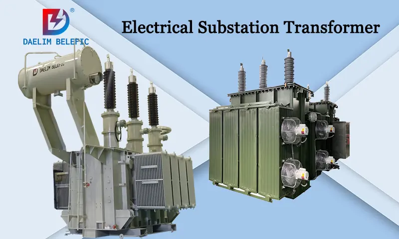
With the continuous development of the world economy and technology, electricity has become an indispensable thing in people’s life and work. Almost everything we see requires electricity. But electricity is not directly available. At this time, we need to convert the voltage into the pressure range that our daily life can use to transmit electricity through the action of the transformer. Today, I will take you to a more in-depth understanding of electrical substation transformer.
DAELIM is more than 15 years experience electrical substation transformer supplier. Over the years, the company has won the trust and praise of the majority of users with reliable product quality and perfect after-sales service. Products have been widely used in power systems and industries around the world, in the future journey. DAELIM will make persistent efforts to provide better products and services to our esteemed customers.
Small-substastion Transformer
Single Phase Pole Mounted Transformer
Table of Content
What is electrical substation transformer?
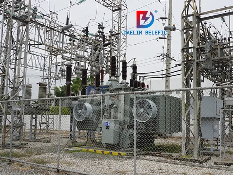
Electrical substation transformers are the most critical primary equipment in substations. Its main function is to increase or decrease the electric energy voltage of the power system to facilitate the reasonable transmission, distribution and use of electric energy. Substation transformers are divided into two categories according to the winding conductor material, copper windings and aluminum windings. Factory substations generally use double-winding transformers.
What is the difference between a padmount transformer and padmount substation?
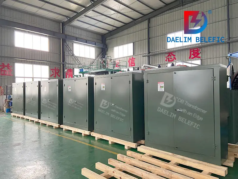
Because of padmount substation’s strong environmental adaptability, small size, compact structure, easy transportation, flexible combination, convenient installation, short construction period, small footprint, low operating cost, no pollution, maintenance-free, easy-to-achieve safety automation, etc. widespread attention. It is widely used in the construction and renovation of small and medium-sized substations in urban and rural areas, factories and mines, and substations for mobile operations.
Therefore, pad-mount substations are easy to transfer and can penetrate into the load center, reducing the power supply radius of the city and improving terminal use. Especially for the transformation of rural power grids and urban power grids, it is known as a feasible model for the construction of modern substations.
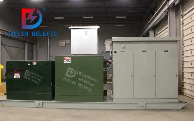
Pad Mount Transformer is a separate transformer device that can connect to high and low -voltage control cabinets, isolation switches, inverters,s and other load equipment. Commonly used for power distribution systems, factories, power distribution stations, residential areas, commercial areas, etc.
General requirements for cooling devices for electrical substation transformers?
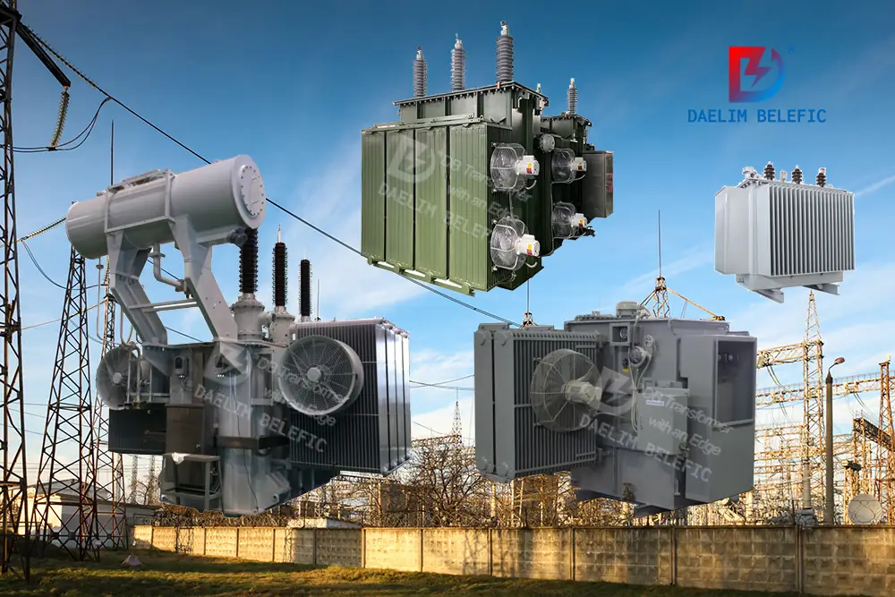
The cooling device of Electrical Substature Transformers is usually designed according to customer requirements and the environment used. There will be oil-natural air-natural cooling (ONAN), oil natural air forced cooling (ONAF), oil-forced air-forced cooling (OFAF), oil forced water forced cooling (OFWF), oil-directed air-forced cooling (ODAF), oil-directed water-forced cooling (ODWF).
How many electrical transformers are in a substation?
Determined according to the number of voltage levels. If it is a 35kv substation, two are generally used, one for 35kv and one for 10kv. No more than three high voltage levels. Special requirements are excluded.
Specification requirements: 220kv substations should be connected to two working transformers with the same capacity from the low voltage of the main transformer, which can be used as a backup for each other and run separately. Each working transformer is selected according to the calculated load of the whole institute. When there is only one main transformer, one of the transformers used should be connected to the external power supply. Therefore, the 220kv substation backup power supply is at least 0 and at most one.
learn more: Basic Guide to Different Transformer Types
What is the main function of the transformer in the power system?
The role of the transformer in the power system is to transform the voltage in order to facilitate the transmission of power. After the voltage is boosted by the step-up transformer, the line loss can be reduced, the economy of power transmission can be improved, and the purpose of long-distance power transmission can be achieved. The step-down transformer can turn the high voltage into the voltage required by the user at all levels to meet the needs of the user.
Get it now: Basic Guide To Oil Immersed Transformer
Are there 2-3 main transformers in the substation?
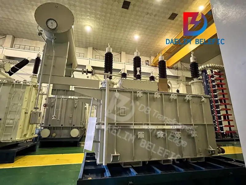
Generally, there are 2-3 units. It is said that there are 8 units, but I have never seen that. It will be very complicated because the power supply and distribution system specification requires two incoming lines from different substations to meet the primary load. Especially important loads plus self-contained generators are already very reliable.
Why is there no fence for the 66kV station transformer and 35kV station transformer of a substation?
- The substation is a special environment. There is an access control system. Generally, people who do not understand electricity do not enter. Therefore, electrical equipment within a specific interval, such as station transformers, do not need fences.
- The purpose of setting fences is to prevent If people enter by mistake, if the station is used in a place that is not easy for people to enter by mistake, such as in a cabinet, on a high platform, etc., there is no need to set
learn more: The Ultimate FAQs Guide To 500 MVA Transformer
How many transformers are usually required in a substation to operate in parallel?
1 Generally, substations require more than two main transformers to run in parallel, and once a transformer fails, it will not cause a complete power outage in the substation.
2 Generally, the main transformers in the substation are in parallel, not in parallel operation, and its high-voltage side or low-voltage side is connected to a busbar.
Structural characteristics of padmounut substation transformer
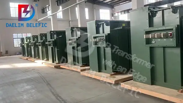
In a conventional padmount substation transformer, its high and low voltage rooms are generally located at both ends of the substation, and the transformer room is located in the middle. The high-voltage room is equipped with load switches, fuses, arresters, etc. with cable (or insulated wire) incoming lines; the transformer room is generally equipped with a zoo–630 kV eight transformers; the low-voltage room is equipped with several sides of the low-voltage distribution screen.
For installation, maintenance and overhaul, the entire padmount substation transformer can be opened on both sides, and each door can be locked with a door lock to prevent non-operators from entering. The padmount substation transformer is also generally equipped with lighting equipment for operation and maintenance. .
In order to facilitate installation and transportation, padmount substation transformers are generally composed of a cabinet bottom made of tip steel, a frame made of angle steel or tip steel, and a box shell formed of bent steel plates.
The padmount top of the padmount substation transformer generally adopts a sandwich air-sakura structure, and is equipped with thermal insulation materials to reduce the influence of solar radiation.
Its cooling channel generally uses cold air from the lower reinforced concrete foundation vent, enters the padmount through the bottom of the transformer, and the hot air is discharged from the upper vent. The transformer room is generally equipped with shutters to facilitate heat dissipation.
The bottom of the box is generally closed with steel plates. The inlet and outlet of the cables (or interwoven insulated wires) are covered with small steel plates, and the air inlet is equipped with a metal mesh, which can prevent small animals from entering people.
It can also play a role in blocking dust. If the box-type substation is used in high-rise buildings and underground facilities, dry-type transformers must be used.
Read my article on:Basic Guide To GSU Transformer
Transformer substation safe distance
For outdoor transformers, the minimum distance between the outer corridor and the surrounding shall not be less than 0.8 meters. The distance between transformer’s outer corridors should not be less than 1.5 meters.
For example, the horizontal distance between the bench-type oil-immersed transformer and the house in the community, if the house is higher than the transformer, the distance between the two should be 1.5 to 2 meters; if the house is lower than the transformer, the distance between the two should be 80 cm.
Basic Theory of Electrical Transformers
Suppose one of the windings is supplied by an AC power source. The alternating current through the windings produces a changing flux or alternating flux winding up.
If any other winding brings close electromagnetic, obviously some part of this flux will connect the second.
For the flux to continuously change its magnitude and direction, there must be a change in the flux linkage in the second winding or coil. According to Faraday’s law of electromagnetic induction, there must be an EMF induced in the second.
If the latter winding circuit is closed, current must flow through it. This is the simplest form of power transformer, and this is the most basic working principle of a transformer.
For better understanding, we try to repeat the above explanation in a shorter form here.
Whenever alternating current is applied to a motorized coil, there will be an alternating magnetic flux around the coil.
If you put another near this first coil, there will be a linkage of the alternating magnetic flux of the second coil.
Since the magnetic flux alternates, there is a significant rate of change in the flux linkage aspect of the second coil. Natural EMF will be induced by electromagnetic induction according to Faraday’s law. This is the most basic conceptual theory of transformers.
Learn more about electrical transformer
The three components of a electrical transformer
- The magnetic flux is produced by the primary winding of the transformer when it is connected to the power supply.
- The core of the magnetic transformer. The magnetic flux generated by the primary winding will pass through the secondary coil and create a closed magnetic circuit with this low reluctance path.
- Transformer secondary coil. The magnetic flux generated by the primary winding, transmitted through the core, will connect with the secondary coil. The windings are wound around the same core and provide the required output transformer.

