How Much Do You Know About Losses In Transformer
The transformer is something we are all familiar with, it can be seen everywhere in our life, and our daily life is inseparable from it. But how much do you know about transformers? Perhaps most people just understand it literally, as a pressure-regulating device. Today, Daelim takes you to learn more about the loss of transformers
Daelim is a transformer manufacturer specializing in the transformer field for over 15 years. Daelim has a very strong technical force and a high-level talent team with complete professional configuration and reasonable personnel structure. Now we have a number of senior experts in the transformer industry, and our products meet multiple standards such as IEEE/CSA/ANSI and have obtained UL qualification certificates. Advocating the concept of brand plus advantages, and taking this as the core of all of Daelim’s work, supports Daelim’s continuous progress. Take the interests of our clients as our guide and insist that the interests of our clients are our own interests. Looking forward to growing and progressing with our customers.
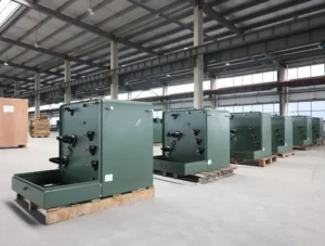
Small-substastion Transformer
Single Phase Pole Mounted Transformer
Oil Immersed Power Transformer
Table of Content
Transformer Loss Type
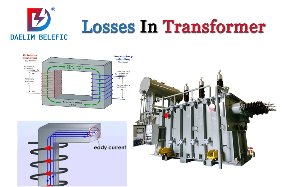
No-load loss (copper loss)
When the rated voltage is applied to one winding of the transformer, and the rest of the windings are open, the active power absorbed by the transformer is called no-load loss. The no-load loss is also called the iron loss of the transformer, which means that it occurs in the transformer core lamination.
When the periodically changing magnetic field lines pass through the material, it is generated by the hysteresis and eddy current of the material, and its magnitude is related to the operating voltage and tap voltage. , the no-load loss is basically independent of temperature, while the load loss is a function of temperature.
Load loss (iron loss)
Load loss is variable loss. It is proportional to the square of the current passing through it. Load loss refers to the load loss at the rated current and reference temperature. The concept of the calculated value, standard value, guaranteed value, and actual measurement of load loss is also the same as that of no-load loss.
But in actual measurement, the applied current cannot be lower than 50% of the rated current. This is the requirement of the new standard, otherwise, the measured value cannot be converted, and even conversion is invalid. The evaluation value of load loss is lower than that of no-load loss, but the absolute value of load loss is large. If it exceeds the same percentage or the same measurement error, the absolute value of z is still large.
learn more: The Ultimate Guide To Core Type Transformers
Transformer Loss standard
National standard 1094-1 stipulates a total loss deviation of +10%, no-load loss, and load loss of +15%, but the total loss should not exceed +10%.
In the standard of transformer loss, for some autotransformers and booster transformers, because of its small impedance, there should be a larger deviation. For transformers with a large tap range, especially when the tap range is asymmetric, special consideration will also be required.
In addition, when the transformer is to be connected in parallel with the existing transformer, a smaller impedance deviation can be specified according to the agreement, but it should be proposed in the bidding stage and specified by the manufacturer and the user through negotiation.
In GB/T6451, the specific value of the loss of different voltage levels and different capacities is specified.
Get it now: Basic Guide To Oil Immersed Transformer
The formula for calculating transformer loss
1) Active power loss: ΔP=PO+KTβ2PK —(1)
2) Reactive power loss: ΔQ=QO+KTβ2QK —(2)
3) Comprehensive power loss: ΔPZ=ΔP+KQΔQ —(3)
QO≈IO%SN, QK≈UK%SN
How to reduce no-load loss in transformer?
Since the no-load loss is an important parameter of the transformer, it only accounts for 20%-30% of the total loss of the transformer. To reduce the no-load loss, it is necessary to reduce the total iron core, unit loss and process coefficient. The main methods to reduce no-load loss are as follows
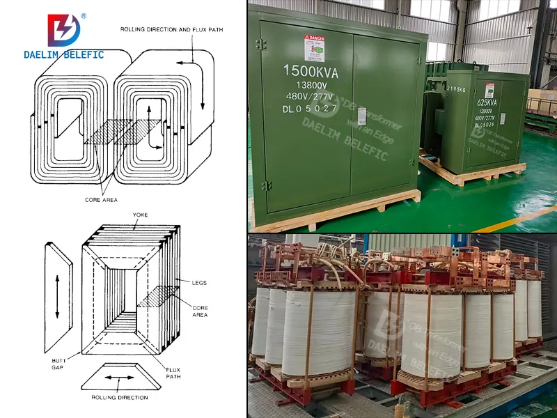
(1) High magnetic permeability silicon steel sheet and amorphous alloy sheet are used. The thickness of an ordinary silicon steel sheet is 0.3~0.35 mm, and the loss can be 0.15~0.27 mm. At the same time, if step stacking is used, the iron loss can be reduced by about 8%. Laser irradiation, mechanical indentation, and plasma treatment can reduce the loss of high magnetic permeability silicon steel sheets. The eddy current loss of amorphous alloy sheets and silicon steel sheets with a silicon content of 6.5% made according to the principle of rapid cooling is smaller than that of general high magnetic permeability silicon steel sheets.
(2) Reduce the process coefficient. The process loss factor is related to many factors such as the material of the silicon steel sheet, whether the punching and shearing equipment is annealed, and the degree of clamping. The tool accuracy, reasonable installation, and adjustment of the punching and shearing equipment are also very important.
Improve the core structure. The iron core is not punched and not tied, and the end face of the glass adhesive tape is coated with solidified paint. The non-magnetic steel plate for the pull plate connects the upper and lower clamps on both sides of the stem. No paint treatment for large-capacity core pieces to improve filling factor and cooling performance. The two yokes of the iron core are made into a solid, flat, and high vertical precision whole by using strong pressure tooling and glue. Reducing the lap width of the core can reduce the loss by 0.3% for every 1% reduction in the lap area. Mixing different grades of silicon steel sheets in the iron core will consume energy, so it should be less or not mixed.
learn more: 7+FAQ About Copper Transformers
How to reduce load loss in transformer?
The load loss accounts for 70%-80% of the total loss, including the DC resistance loss (basic loss) of the winding, the eddy current loss in the wire, the circulating current loss between the parallel wires, the lead loss and structural parts (such as splints, steel pressure plates, box walls, bolts, iron cores) stray losses of pull plates, etc.). The main ways to reduce load loss are as follows:
- Limit the additional loss caused by magnetic leakage. Carry out the ampere-turn balance calculation and adjust the ampere-turn according to the result. The windings are arranged in “low-high-low” or “high-low-high” to limit the width and thickness of the flat wire. Calculate the magnetic field and select the most suitable transposition method. wire or combination wire.
- Reduce the size of the main and vertical insulation structures. The technology of “iso-impulse voltage gradient” distribution on the high-voltage winding can reduce the size of the longitudinal insulation. Between the windings, thin paper tubes and small oil gaps are used for the main insulation. Corrugated paper is used as the main insulation. The shape of the bit line takes the split forming angle ring as the structural part. The inner diameter of the winding is wound on the insulating paper, but the axial oil channel is arranged in the middle of the line segment. The acetal enameled wire is mostly used instead of 0.45mm thick paper. Because the first two turn insulation is 2X (0.056~0.079) mm, the winding filling factor is high and meets the requirements of turn insulation, and the barrel winding is mostly used. Because there is no oil passage between the cakes, the cooling mainly depends on the axial vertical oil passage. Good heat dissipation, filling factor and impact characteristics are good, the ampere-turn is uniform, the short-circuit force is small, and the distance between the main insulation (diameter and end) is appropriately reduced.
- The relevant process is adopted according to the calculation. According to the impact calculation, it is determined that the longitudinal insulating structure spacers, struts, and chamfers of metal parts maintain a good shape. Calculate the leakage magnetic field and eddy current distribution. Guide the transposition method. Set up special shielding to ease the electric field. The voltage-regulating winding adopts one layer and one tap. The assembled inner winding is directly wound on the insulating cylinder. The height and diameter tolerance are strictly controlled. The gap in the sleeve is small. Use Dinaisong paper tape to dry the windings at the location and place them in the insulation drying room to prevent moisture.
- Use low-loss and low-resistance wires. It is made of oxygen-free copper wire and drawn by the upward drawing method, such as using a copper continuous extruder. If it can be used in transformers, it can save energy and reduce volume, and it has certain application prospects.
- Using the characteristics of an insulating structure to design can reduce the volume. Use the liquid dielectric properties of the transformer oil to properly set up the covering layer, barrier, shielding, and insulating layer. Use the “distance effect” of oil to add partitions to form small coil gaps. Use the “volume effect” of the oil. Use corrugated paper to use the “thickness effect” of the insulating layer in the oil. The insulation of the package increases the breakdown voltage, but it should not be too thick. Use the characteristics of the distance between the separator in the oil and the maximum field strength to set the separator.
Get it now: The Ultimate Guide To 1250 kVA Transformer
Adopt advanced insulation structure. The use of suitable windings to increase the filling factor adopts a new type of spiral (or continuous) winding with axial oil passages to effectively reduce the winding volume. The compression structure of non-metallic or non-magnetic material is used in the concentrated part of the leakage magnetic flux, and the electromagnetic shielding is used to make the leakage magnetic flux groove circuit, which can reduce the load loss by about 8%.
Daelim Transformer Manufacturer
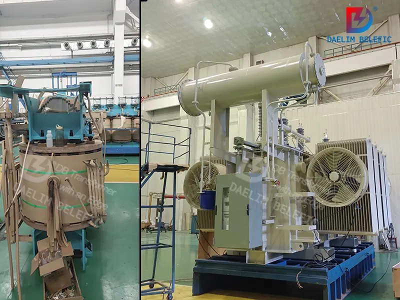
Daelim is a professional transformer manufacturer in China.Daelim transformer adopts advanced materials and technical processes, which effectively reduces transformer losses and improves transformer efficiency and performance. Daelim transformers have undergone rigorous experimental tests every day, and UL regularly comes to the factory to supervise all aspects of production.
Therefore, the Daelim transformer has very good quality and performance, and also provides you with a two-year or even longer product warranty period. Welcome to contact Daelim through the mail (serveric1@daelim-electric.com) and the phone (86-13121593340).