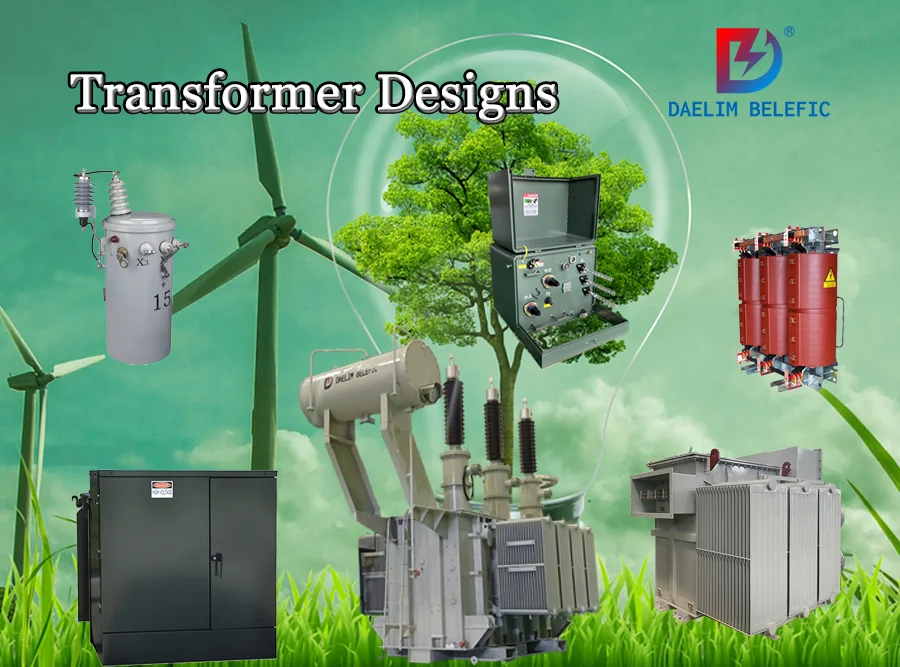
The Ultimate Guide To Transformer Designs
The transformer is the key equipment in the power system. Transformer design is particularly important. Including transformer type, standard, efficiency value, loss, etc. This article will tell you about the related problems of transformer design.
Daelim is the world’s top transformer supplier and manufacturer. Over 20 years of experience in overseas transformer projects allows it to design transformers of all standards, such as IEEE, ANSI, CSA, AS, NZS, IEC, GOST, etc.
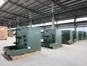
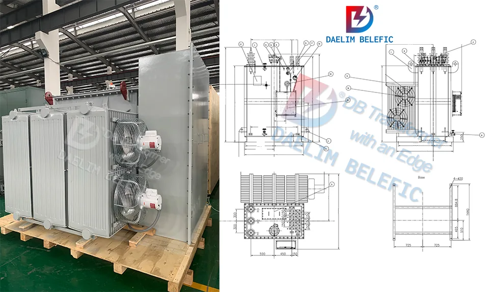
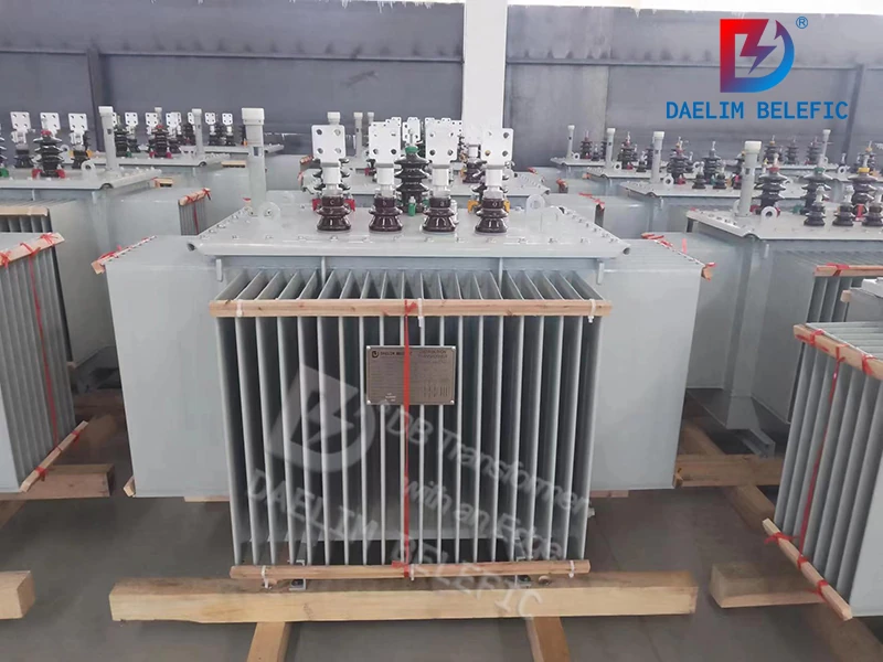
Small-substastion Transformer
Single Phase Pole Mounted Transformer
Table of Content
What Is The Basic Design Of A Transformer?
There are three basic transformer design types: core, shell, and toroidal. There is also another design called the dry-type transformer.
Core Design
Regarding core design transformers, the two windings (primary and secondary) are completely encased in the magnetic core. Depending on how the magnetic core is shaped, core-type transformers can be divided into different groups. Core-type transformers come in two types:
- Single-Phase Transformer Design – absorbs single-phase AC voltage and generates single-phase AC voltage according to the transformer’s ratio.
- Three-Phase Transformer Design – converts one type of AC voltage to another type of AC voltage.
Shell Type
Shell-type transformers can be distinguished based on the design of the magnetic core and the placement of the transformer winding. Shell-type transformer winding is located on the central limb of the core, while the other stems are utilized for mechanical support.
Toroidal
Toroidal transformers, utilized as power transformers, have their main and secondary coils wound around a spherical core. Since shorter coils are used, resistive losses or winding losses are reduced, and total efficiency is increased thanks to the toroidal transformer’s unique structure.
Dry Transformer Design
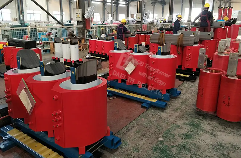
A cast resin-type transformer is solid, commonly categorized as a dry transformer design. It has no revolving components. To operate effectively, these particular transformers make the best use of environmentally friendly temperature insulation methods.
Unlike liquid-type transformers, a dry transformer adjusts the voltage, which requires additional resources like fire and oil.
What Are The Major Parts Of A Transformer?
A magnetic core, primary, and secondary winding are the three fundamental components of a transformer. An alternating current (AC) source is connected to the primary winding. In doing so, it generates a magnetic field that revolves around the coil.
This results in an electromotive force being exerted on the secondary winding. When the circuit closes, alternating current will flow through the secondary winding. The windings provide power to the magnetic core, commonly made of laminated steel sheets, and provide a path of ensuring minimal for the magnetic field.
Both the outgoing voltage and source voltage are proportional to the number of turns in each winding. Inside a step-up transformer, the secondary winding has more turns than the primary winding, while the opposite is true for a step-down transformer.
What Is The Classification Of A Transformer?
Transformer Design Calculation Based On The Number Of Phases
Single Phase Transformer Design
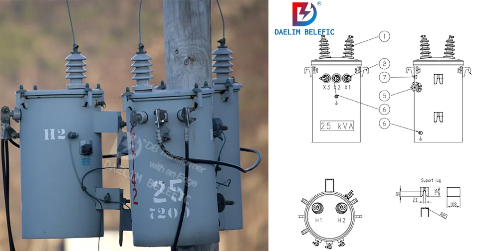
A single-phase transformer must be used if the electricity supply is switching single-phase. It primarily comprises two windings, primary and secondary, which do not connect electrically but are connected magnetically via a channel of low reluctance known as the “Core.”
This phenomenon is referred to as the photoelectric effect. Before the direct current (DC) is used or supplied into the electricity network, it must be converted to alternating current (AC) for public use.
Three Phase Transformer Design
Transformers can be converted to three-phase operation by connecting three single-phase windings. Both sets of transformers’ secondary windings are linked, and the primary windings of the first three are connected to those of the last three.
Transformer Design Calculation Based On Construction
Center
The coils of a core-type transformer are located on two arms at right angles to one another and wrap around a substantial section of the core. The core’s stepping increases along with the transformer’s size or rating. Circular cylindrical coils are often used in high voltage core type transformers, but this design is only used in small and medium capacity models
Shell
Transformers of the shell variety have coiled main and secondary windings that enclose the center. This configuration is also referred to as the “Sandwich” kind. For high-voltage transformers, the shell-type structure is typically preferred.
Berry
Berry transformer, also known as a toroidal transformer, is frequently used in home devices and many other high-tech electronic equipment. This type of transformer has two primary applications: power and isolation.
Transformer Design Calculation Based On Function
Power Transformers
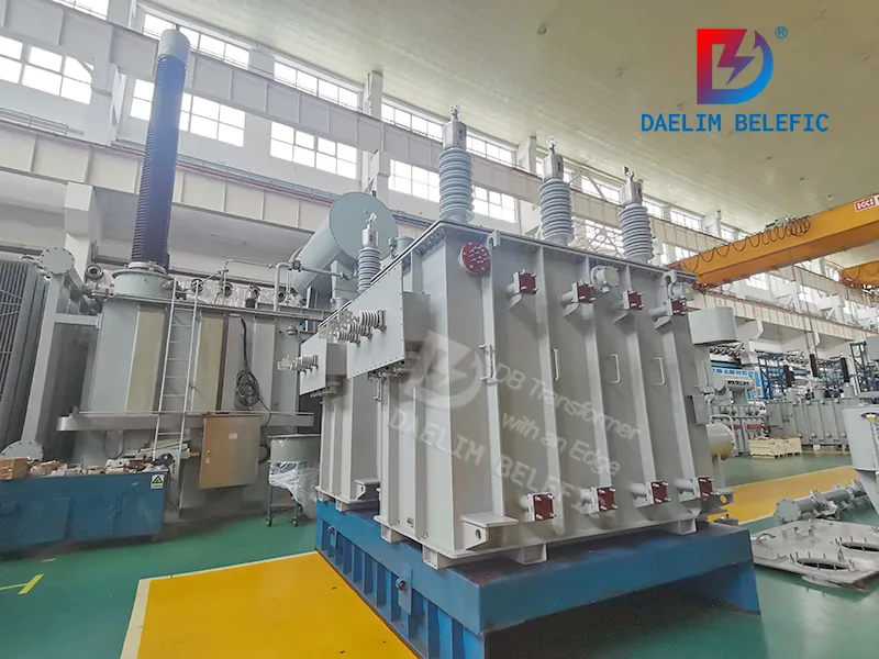
Transmitting power from generation facilities to the substation close to load centers can’t be done without power transformers. Large transformers, called step-up voltage transformers, increase the voltage at the power plant. Power transformers are intended to run at full capacity with the highest possible efficiency.
Get it now: The power line transformer!
Distribution Transformers
Distribution transformers work under varying load situations and are relatively modest. Depending on the required voltage, the distribution transformer delivers power from the substation to the different loading areas.
Read more: How to produce a distribution transformer?
Instrument Transformers
In an AC system, instrument transformers function to measure electrical quantities, including voltage, current, power, energy, power factor, and frequency. In order to keep the power grid safe, protective devices often work in tandem with instrument transformers.
Welding Transformers
A welding transformer is an important piece of equipment that decreases the voltage supplied by the power source. It operates by converting the AC from a power outlet to a strong amperage, low-voltage current suitable for welding. The main and secondary taps of the welding transformer are used to control the voltage level used in welding.
Transformer Design Calculation Based On The Number Of Windings
Single-winding Transformer
An autotransformer, or single-winding transformer, is a single-winding electrical transformer. It has a single coil functioning independently, not to any mechanical process. Its construction is identical to that of a two-winding transformer; however, the connections between the primary and secondary windings are reversed.
Multi-winding Transformer
Multiple main or secondary coils are wound on a similar laminated core in a multi-winding transformer. It operates in the same way as any other transformer.
The primary and secondary voltages, turn ratios, and currents are all calculated similarly, but the voltage polarities of each coil winding, with the dot convention, conveys different marking polarity (positive or negative) when put together.
Learn more: Electrical transformer
What Are The Steps To Design The Transformers?
Step 1: Test The Magnetic Core
Test a large steel bolt as a transformer’s magnetic core. First, check the bolt for magnetism by holding it to a kitchen magnet. If the magnet sticks, you can use the steel boat of your transformer’s core.
Step 2: Wrap The Bolt
Wrap insulating tape around the steel bolt to separate the windings from the core. Peel the ends of the coated copper wire after cutting it into two uneven lengths. By using the same wire, you can guarantee that the coil winding ratios are identical.
Step 3: Wrap The Wire In Tape
Coil the two copper wires around the core at least 12 revolutions. Both the main and secondary windings of the transformer will be constructed out of the wire coils. Keep the exposed ends of the wires dry. Leave a space between the primary and secondary windings and secure it with insulating tape
Step 4: Connect The Secondary Coil To The Bulb
Connect the secondary coil’s endpoints to the bulb. Ensure they do not contact each other to prevent the bulb from igniting. If required, use electrical insulation tape to secure the wires in position.
Step 5: Connect The Primary Coil To An AC Power Source
Choosing an AC power supply with a power button, voltage control settings, and an input fuse will help offer safety and isolation from “wall” power. Start operating with the AC power at its lowest setting and gradually raise it to see the bulb’s brightness adjust. When you turn on the power, the lamp should light up. If not, double-check your connections and start again.
Step 6: Observe Safety Precautions
If you smell burning, quickly disconnect the primary coil ends from the power source. This is an uncommon scenario because the transformer should offer enough resistance to prevent an excessive current from passing through, but it’s still best to remain cautious.
If the transformer is burning, determine whether the cause of the short circuit is the connection between bare wires. Tape the naked wires, and you can try again.
Step 7: Check The Luminosity Of The Bulb
The bulb’s brightness will increase in the step-up arrangement. In addition, the transformer core will start acting as an electromagnet. You can test if it is an electromagnet by putting metal objects against it.
Keep reading: Dry Transformer VS Oil Transformer
What Are The Design Parameters Of Transformers?
Main And Second Voltage
The sum of all voltages received on the input side of a given transformer is referred to as the main voltage.
In contrast to this, the second voltage is the electricity that is produced by the transformer.
If the available supply voltage is 414 V three-phase and the desired output voltage is 240 V single-phase, you should use a transformer with 415 V input and 240 V output ratings.
Kilovolt-Amps (KVA) Rating
A KVA stands for 1,000-volt amps. A volt is a unit of electrical pressure, while an amp is a unit of electrical current. KVA is affected by current, voltage, and power factors. During the process of selecting a transformer and designing one, it is vital to measure the KVA. This is the highest apparent voltage that a transformer can take.
Operational Frequency
A transformer runs at a specified frequency. The transformer frequency determines the magnetic current, rated current, and KVA. As a consequence of this, the transformer is required to operate at the required frequency. Its rated frequency should always be identical to the input power source and the bandwidth of the load.
Read my article on Oil Type Transformer
How Do You Design The Capacity Of A Transformer?
You can design a transformer’s capacity by considering the following elements: total volume, weight, cost, and loss. All of these quantities change with the ratio r = m/ AT. If you choose a high value for ‘r,’ the flux will be increased, requiring a big cross-section that will raise the volume, weight, and cost of iron while also causing more iron loss.
As the value of ‘AT’ plummeted, so did the volume, weight, and cost of copper and the amount lost. As a result, ‘r’ is a controlling factor for the volume, weight, cost, and loss.
What Are Typical Transformer Losses?
Transformer losses are made up of coil and core losses caused by electrifying the laminated steel frame. The charging of the laminated steel core causes core losses. These losses are nearly consistent from no-load to full-load and are around 0.5% of a transformer’s full-load capacity for the average 150 C rise transformer. Here are some typical transformer losses.
Resistive Waste
The power loss in a transformer caused by the resistance of the copper wire used to make the windings is called resistive waste. When higher frequencies lead electrons to move further toward the outside perimeter of the conductor, electrical disruptions known as harmonics reduce wire size and increase resistive loss.
Hysteresis Loss
Hysteresis loss is the loss generated by the magnetism that stays in a medium after the magnetization has been neutralized. Magnetic domains are tiny areas of a magnetic substance that work together when subjected to a magnetic field.
Magnetic domains contain magnetic characteristics and migrate in iron when exposed to a magnetic environment.
Keep reading: 3 Phase Transformer Power Transformer Manufacturer
What Are The Important Factors Engineers Need To Consider When Designing A Transformer?
Tap Changer
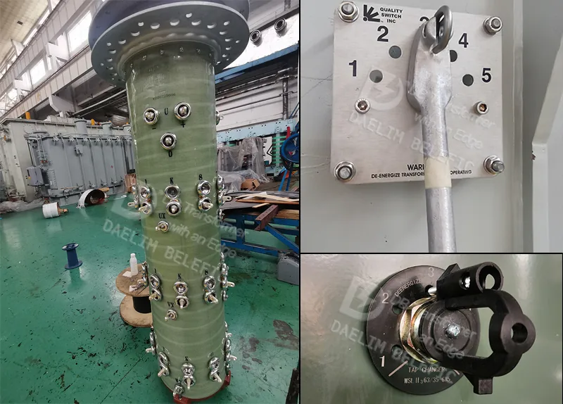
Tap changer alter the power input between the high and low windings. Typically, manual de-energized tap changing is performed to correct for changes in transformer ratios and overall voltage level. You should choose the transformer tap depending on the highest no-load voltage.
Different tap changers for different types of transformers. The TAP Changer designed by Daelim can use MR, Qualitrol, Quality, and other internationally renowned brands.
Transformer Failures
Transformer failures are quite uncommon. But, in high-rise buildings and other structures with limited escape options, the consequences of larger transformer failure can be severe. A well-designed transformer protective system can reduce the degree of damage to every transformer type.
What Factors Affect The Price Of A Transformer?
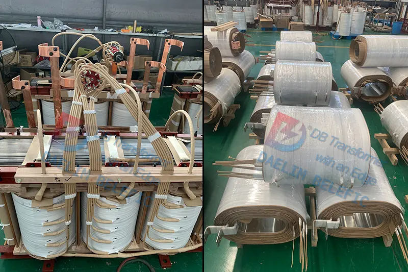
Production
To prevent damage, winding insulated wires requires great attention. The coil must be manufactured with human accuracy to ensure quality and reliability. Soldering is also necessary for the job, which charges huge amounts.
Margin Tape
For each breeze, a margin tape matches with clearance ranges. This, like soldering, falls under the overhead category since it is part of the manufacturing process.
Most of the cost of power transformers is tied to the manufacturing process and manual labor. Since copper is rare, the wire size also affects the transformer’s price.
Flying Leads
Flying leads to adding to the cost by reducing the size of the extra rail spool. Since flying leads should be manually placed on the board, it raises production costs.
Conclusion
Creating and designing a transformer can be expensive and difficult. Before deciding on a design and type of transformer, research and know the different uses of various transformers. Know what’s best for your location to minimize costs but still get the best quality power transformer.
Daelim’s professional technical team can customize the most suitable transformer solution for you.