The Ultimate Guide to Electrical transformer
This article is about the electrical transformer information, there will have the regular requirement and design and special tech spec requirement.
Daelim can produce all type of transfomrers, include oil immersed transformer and dry typr transfromer, they all belong to electrical transformer.
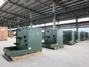
Pad-mounted Transformer
Dry-type Transformer
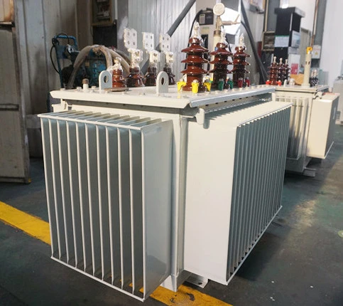
Oil immersed transformer
Table of Content
Regular basic Requirements of the electrical transformers
The transformer shall be oil filled.
All electrical devices on the transformer will be wired to the terminals in the control cabinet mounted on the transformer tank.
Power supply for forced air and/or oil-cooling equipment shall be 440 volts, 3-phase, 60 Hz. Cooling fans and/or circulating oil pumps shall be thermostatically controlled.
Standard transformer impedance and Dyn-11 vector grouping shall be provided.
High voltage and low voltage terminal boxes shall have removable end panel and be large enough for long barrel compression lugs for terminating copper cables with approved stress cones. A chamber shall be provided equipped with removable links between incoming cable terminations and transformer primary winding connections
High voltage and low voltage terminal boxes shall be mounted on the sides of the transformer.
Transformers shall be equipped with a terminal junction box for controls, protection alarms and space heaters wired to terminal strips for COMPANY connections.
All connection points including terminal pads shall be copper and tin-plated.
Transformer windings shall be properly wedged and braced to prevent movement due to shipping or mechanical stresses imposed by heavy currents accompanying the starting of large motors, switching surges and short circuits. Copper windings shall be furnished.
The transformer shall be capable of operating continuously above or below rated voltage or below rated frequency at maximum rated kVA for any tap, without exceeding the 65°C average temperature rise for:
a) Secondary voltage and volt/Hz with ±5% of rating.
b) Load power factor down to 0.8 lagging.
c) Frequency as low as 95% of rated.
Try for free Where is a 33 kv Distribution Transformer Used for?
Wiring requirement of the electrical transformer
All wiring shall be continuous from device to terminal or terminal-to-terminal. Splicing of two wires is not acceptable. Not more than two wires shall be connected to one terminal screw. All wiring shall be marked on each end with permanently embossed wire markers of the heat shrinkable type. Wire markings reflecting phase indication shall be provided at the ends of all phase connections.
Wire markers shall accurately reflect information on the wiring diagrams.
All wiring shall be adequately protected against contact with sharp edges and neatly bundled and secured with wire ties or tie-wraps.
The neutral of the low voltage, wye-connected windings shall be fully insulated and brought to the manufacturer’s standard terminal chamber location. The neutral bushing Basic Impulse Level (BIL) shall be the same as the phase winding BIL.
The transformer assembly shall be rigidly constructed to allow mounting pad level variations of ±3.2mm over the length and width of the transformer base.
A liberal coat of mastic to prevent rusting shall protect the underside of the transformer enclosure and bottom of the tank, which will be in contact with the transformer foundation. Tank bottom shall be raised from the normal foundation and braced to prevent sagging.
The transformer shall be completely factory-built, assembled, wired and tested. Transformer shall be furnished with zinc oxide station type lightning arrestors (one per phase), mounted inside the air terminal chamber. Rating of the arrestors shall be coordinated with the BIL rating of the transformer.
The primary and secondary windings shall be constructed from high conductivity copper. All turns of windings shall be adequately supported to prevent movement. The high voltage winding shall be of layered winding and the low voltage winding shall be of foil winding using Copper sheets.
The core and coil assembly shall have the core and coils rigidly connected. The core/coil assembly shall be mounted on the cover plate so that the assembly could be removed from the tank using the suitably placed lugs provided on the cover plate.
To ensure that the core and coils of transformers are seated on the floor of the tank, supporting frames shall be designed to accommodate variations in tank height. The core and coil assembly shall be rigidly connected to the tank and suitably closed lugs shall be provided for removing the core and coil assembly from the tank.
Construction features shail permit local repairs to be easily carried out in the event of equipment failure.
Get the What is a 50 kva Distribution Transformer? now
The Tank of the electrical transformer
The transformer tank shall be fabricated from steel and shall be of robust construction. Care should be taken at the manufacturing stage so as not to have leaks during transportation or when the transformer is continuously operated at rated power.
With the exception of radiator elements, all external joints shall be seam welded. There shall be only one vertical seam weld for the fin radiator and the other three vertical corner edges of the transformer shall be formed by bending. Corner ribs shall be avoided for the fin radiator. The bearing surface of the tank to which bushings are clamped shall be substantially flat.
All matching faces of joints shall be made oil tight and finished with a smooth surface to ensure that the casketing materials make a satisfactory joint.
Flanges and covers of tanks shall be of sufficient thickness to prevent any depression occurring, which would retain water around the bolts. The horizontal edges of the cover plate shall be bent over the tank flange to facilitate water dripping out of the tank. The bent collar width shall be about 10mm to 15mm.
All the nut and bolts used shall be hot dip galvanized and spaced at sufficiently close intervals to avoid buckling of either flange or covers and shall provide reasonably uniform compression of the gasket.
Each transformer shall be provided with a minimum of two closed lifting lugs. The minimum diameter of the hole or width of the slot shall be 25 mm. The two lifting lugs shall be located such that there would be a minimum of 50 mm between the lifting chain and the nearest part of the bushings.
All transformers shall be suitable for outdoor mounting on pole or plinth platforms and shall have four mounting lugs with 12 mm diameter holes suitable for bolting the transformer to the platform. Bolt hole spacing shall be as specified by the purchaser to suit mounting requirements.
Read on 69KV MOBILE SUBSTATION WITH GIS
The Accessories of the electrical transformer
All standard accessories shall be provided including and in addition to the following items: –
a)A magnetic liquid level gauge with alarm/trip contacts.
b)Thermometers and Thermocouples for monitoring winding and oil temperatures, with alarm/trip contacts.
c)Pressure relief device such as to direct the oil away from the transformer.
d)Provision for lifting and jacking.
Read my article on All Things You Need to Know About 75 kva Transformer
Coatings of the electrical transformer
All standard accessories shall be provided including and in addition to the following items: –
a)A magnetic liquid level gauge with alarm/trip contacts.
b)Thermometers and Thermocouples for monitoring winding and oil temperatures, with alarm/trip contacts.
c)Pressure relief device such as to direct the oil away from the transformer.
d)Provision for lifting and jacking.
Try for free information about the Some tips about 225 kva transformer
The Accessories of the electrical transformer
Transformer assembly (including tank, radiators, throats, and terminal chambers) shall be cleaned and sealed with a moisture resistant, long-life coating in accordance with NEMA C57.12.28-1999.
Finish coat shall have a nonmetallic pigment surface. Color of finish coat shall be light-gray number 61 in accordance with ASTM D1535-2001 (Munsell Notation 8.3G 6.10/0.54) and covered with an epoxy or acrylic coat for protection against chalking and fading caused by environmental conditions.
A quart of touch-up paint shall be provided for the finish coat. A Material Safety Data Sheet (MSDS) shall be provided.
The base of the tank and channels, unless made of stainless steel,shall be coated with an asphalt-based paint or mastic.
Data for qualification of the proposed coating system shall be provided.
Primary winding shall have a manual tap changer, in accordance with Section 5.1.1 of ANSI C57.12.10-1997, for de-energized operation.
Unless otherwise specified on the purchaser’s PIP ELSTR01D Data Sheet, the tap changer shall be five-position with four 2-1/2% fullcapacity taps, two above and two below the rated primary voltage.
Keep on reading The Ultimate Guide to 300 kVA Pad Mounted Transformer
Customized electrical transformer
Daelim is a professional electrical transformer supplier. It has a professional transformer technical team, and can customize various types of electrical transformers according to your parameters and technical requirements of the transformer. Daelim’s electrical transformers have been exported to the United States, Canada, Mexico, Australia, Chile, El Salvador, Panama, Ecuador and other North and South American regions. And won unanimous praise from customers for the quality of transformer products. If you also have electrical transformer needs, you can cooperate with Daelim with confidence.