Come to know more about DAELIM 15 mva transformer
In power plants and substations, the transformers used to transmit power to the power system or users are called power transformers. In this article we will discuss 15 mva transformer, also some tips about power transformer.
Except power transformer, other transformers are used for power distribution, generally called distribution transformers, with a slightly smaller capacity.
Pad-mounted Transformer
Dry-type Transformer
Oil immersed transformer
Click below for quick review of 3 phase transformer
What is a 15 MVA transformer?
15 mva is the capacity of this transformer, 15 MVA = 15000 KVA.
For such capacity, the high voltage could be 115kv, 138kv, 161kv, 230kv.
15 mva transformer price depends on the voltage, if 230kV the estimated weight is USD 450K~500K.
Let’s know learn more about the 500kVA transformer
What are the specifications of the 15mva transformer?
Take 230kV 15 mva transformer specification as an example, below is a 15 mva transformer data sheet.
Power Transformer, Three Phase, KNAN/KNAF1/KNAF2 10000/12500/15000KVA 230/24.94KV | ||||
| ||||
Project | DESCRIPTION | UNITS | OFFERED | |
A | GEBERAL BACKGROUND |
|
| |
A.1 | Provider | – | TRITON TRANSFORMER | |
A.2 | Representative | – | TRITON TRANSFORMER | |
A.3 | Brand | – | TRITON TRANSFORMER | |
A.4 | Model | – | S11-15000-230/24.94 | |
A.5 | Delivery term |
| CIF | |
A.6 | Type | – | Oil immersed | |
A.7 | Rules | – | IEEE C57.12.00 IEEE C57.12.90 | |
A.8 | Amount of equipment to supply |
| 1 | |
B | ENVIRONMENTAL CHARACTERISTICS AND NETWORKS |
|
| |
B.1 | CHARACTERISTICS OF THE NETWORKS TO WHICH THE EQUIPMENT WILL BE CONNECTED |
|
| |
| Voltage | frequency | Hz | 60 |
|
| Nominal voltage(NSEG 8.E.n.75) | kV | 230 |
|
| Nominal voltage(NSEG 8.E.n.76) | kV | 25 |
B.2 | ENVIRONMENTAL CONDITIONS OF THE INSTALLATION PLACE |
|
| |
B.2.1 | Maximum ambient temperature | °C | 40 | |
B.2.2 | Minimum ambient temperature | °C | -40 | |
B.2.3 | Average daily maximum temperature | °C | 25 | |
B.2.4 | Maximum height of sea level (see Note 1) | m | 2000 | |
B.2.5 | Average annual rainfall | mm | According to project | |
B.2.6 | Maximum wind pressure | kg/m2 | According to project | |
C | GENERAL CHARACTERISTICS |
|
| |
C.1 | Standards used in manufacturing: |
| IEEE C57.12.00 | |
D | SERVICE TECHNICAL CHARACTERISTICS |
|
| |
D.1 | Primary winding tension | kV | 230 Delta | |
D.2 | Secondary winding tension | kV | 24.94/14.4 | |
D.3 | N° phases |
| 3 | |
E | TECHNICAL CHARACTERISTICS |
|
| |
E.1 | Type of cooling: |
| KNAN/KNAF1/KNAF2 | |
E.2 | Powers at 65º C according to type of cooling |
|
| |
E.2.1 | -Power KNAN | kva | 10000 | |
E.2.2 | -Power KNAF1 | kva | 12500 | |
E.2.3 | -Power KNAF2 | kva | 15000 | |
E.3 | Impedance at 10000 KVA, 65º C, Nominal Voltage | % | 7 | |
E.4 | Temperature rise coiled to the installation temperature (winding- oil – hottest point) | ºC | 65 – 65 – 80 | |
E.5 | Nominal Voltage (between phases): |
|
| |
E.5.1 | – Primary winding | kV | 230 Delta | |
E.5.2 | – Secondary winding | kV | 24.94 Wye/14.4 | |
E6 | Winding material |
| Copper | |
E.7 | Winding Connection |
| DYN1 | |
E.8 | Basic Impulse Level Rolled Up |
| IEEE C57.12.00 | |
E.8.1 | – Primary winding | kV | 900 | |
E.8.2 | – Secondary winding | kV | 150 | |
E.9 | Polarity |
| (-) | |
E.10 | No load Losses at Nominal Voltage at 10000kva |
|
| |
| 100% Vn | KW | As per the design | |
E.11 | Load losses at full load at Nominal Voltage at 10000kva |
|
| |
| 100% Vn | KW | As per the design | |
E.12 | Total losses | KW | As per the design | |
E.12.1 | Losses Tolerance |
| As per IEEE C57.12.00 | |
E13 | Tapping on LV |
|
| |
E13.1 | Tapping method |
| DETC | |
E13.2 | Tapping range |
| ±2*2.5% | |
E14 | Noise level Max | dbA | 73 | |
E.15 | CONTACTS OF CONTROL ACCESSORIES, AND ADDITIONAL ACCESSORIES |
|
| |
E.15.1 | Welded top cover with round manhole in cover |
| Included | |
E.15.2 | Provisions for jacking, skidding, and lifting |
| Included | |
E.15.3 | Nameplate |
| Included | |
E.15.4 | Two ground pads copper |
| Included | |
E.15.5 | De-energized tap changer |
| Included | |
E.15.6 | Pressure vacuum gauge with contact bleeder valve |
| Included | |
E.15.7 | Pressure relief device with auxiliary contacts with flag |
| Included | |
E.15.8 | Winding Temp. with contacts |
| Included | |
E.15.9 | Liquid Level Gauge with contacts |
| Included | |
E.15.10 | Oil Temp. Indicator with contacts |
| Included | |
E.15.11 | Sudden pressure relay with seal in relay |
| Included | |
E.15.12 | Control box NEMA 4X type(single phase 120VAC power supply) |
| Included | |
E.15.13 | Fans |
| Included | |
E.15.14 | Detachable Radiator |
| Included | |
E.15.15 | MR CT on HV,LV and LV Neutral bushing |
| Included | |
E.15.16 | Surge arrester on HV and LV |
| Included | |
E.16 | Bushing: |
|
| |
E.16.1 | Manufacturing Standard |
| IEEE | |
E.16.2 | HV bushing type |
| Porcelain | |
E.16.3 | Mounting positon |
| ANSI Segment 3 | |
E.16.4 | Insulator color |
| Light Grey | |
E.16.5 | LV bushing: |
| Porcelain | |
E.16.6 | Mounting positon |
| ANSI Segment 1 | |
E17 | Transformer color |
| ANSI Grey 70 | |
F | OIL PROPERTIES |
|
| |
F.1 | Commercial designation |
| RAPO | |
F.2 | Type |
|
| Vegetable oil |
F.4 | PCB |
| NO | |
G | Dimension and weight |
|
| |
G.1 | Total Dimentions |
|
| |
G.2 | Height | mm | As per the design | |
G.3 | Depth | mm | As per the design | |
G.4 | Width | mm | As per the design | |
G.5 | Weight |
|
| |
G.6 | Oil | KG | As per the design | |
G.7 | Total | KG | As per the design | |
H | TESTS ACCORDING TO CONSTRUCTION STANDARD |
|
| |
G.1 | Routine Tests as per IEEE C57.12.90 | – | YES | |
I | Warranty | – |
| |
I.1 | 2 year | – | YES | |
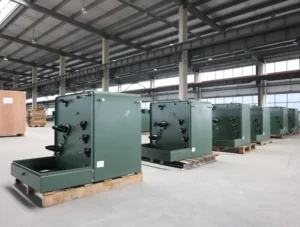
What are the parts of a 15mva transformer?
Inside the 15 mva transformer, it has iron core, winding, iron yoke, tap switch, oil. Outside the 15 mva transformer, it has bushings, oil conservator, moisture absorber, radiator, fans, lifting barrel, transformer body, gas relay and other protection accessories.
Keep on reading Electrical transformer – DAELIM BELEFIC
How much oil is in a 15 MVA transformer?
For above 10000/12500/15000KVA 230/24.94KV power transformer, the total oil weight is 20500kg.
You may interested in Introduction of a special transformer – furnace transformer
How much does a 15 mva transformer weight?
For above power transformer, 15 mva transformer weight 52000kg.Tank and accessories weight 11000kg, active part 21000kg.
Know more about The most complete explanation of grounding transformer
How big is a 15 mva transformer?
15 mva transformer dimensions: Length*Width*Height 6250mm*4895mm*6510mm
Try for free High voltage transformer – 138kv power transformer
Several tips about 15 mva power transformer.
What is a forced oil circulation air-cooled transformer?
Answer: Forced oil circulation air-cooled variable pressure installation of submersible oil system is in natural oil circulation air-cooled variable pressure
On the basis of the cooling system called “strong oil circulation cooler”, a submersible oil pump is installed in the pipeline connecting the transformer body and the lower part of the radiator, so that the insulating oil circulates rapidly under the action of the oil pump to achieve the purpose of heat dissipation.
The number of groups of forced oil circulation radiators is much less than that of oil natural circulation transformers, radiators
The 180MVA transformer only needs 4~5 groups. Forced oil circulation transformer cooling Figure 4-60 Forced oil.
Get the HONDURAS CUSTOMER now
How is transformer insulating oil extracted?
Answer: Transformer oil is a complex hydrocarbon extracted from petroleum, generally
Distillate in petroleum can be made into transformer after alkaline washing, bleaching purification and degreasing treatment.
Oil. When using, it should be mixed with other types of oil in a certain proportion, and then add a These chemicals are used to improve its performance and become the actual transformer oil we use.
Read on KAZAKHSTAN CUSTOMERS
What requirements should be met when the transformer adopts oil injection and nitrogen discharge?
(1) The insulating oil must be purified, and the oil injected into the transformer must meet the relevant regulations on electrical strength, water content and dielectric loss.
(2) The residual oil in the fuel tank should be drained before oil injection and nitrogen removal.
(3) The oil pipe should be made of steel pipe, and the interior should be thoroughly derusted and cleaned. If an oil-resistant rubber hose is used, it must be ensured that the rubber hose does not pollute the insulating oil.
(4) The insulating oil should be injected into the transformer from the lower valve of the transformer through the degassing and oil purification equipment, and the nitrogen should be discharged through the top; the oil should be injected to the top of the oil tank to exhaust the nitrogen. Finally, it should be more than 100mm above the upper edge of the iron core, and the resting time of the oil should not be less than 12h.
Read my article on Know More About The Main Transformer – DAELIM
What are the requirements for transformer winding temperature?
The maximum temperature of A-class insulation transformer windings cannot exceed 105C. If it is continuously operated at this temperature, the insulation will age quickly and the service life will be greatly reduced. According to the test, if the winding temperature is kept at 95°C, the service life is 20 years; the temperature is 105C, the service life is 12 years, and the temperature is 120C, the service life is 2 years. It can be seen that the service time of the transformer mainly depends on the operating temperature of the winding.
Try for free information about the The Ultimate Guide to Liquid Filled Transformer
What are the requirements for the storage of the transformer after it arrives at the site?
The storage of the transformer after arriving at the site should meet the following requirements:
(1) The radiator (cooler), connecting pipe, safety air passage, oil purifier, etc. should be sealed;
(2) Meters, fans, submersible pumps, gas relays, airway baffles, temperature measuring devices and insulating materials should be placed in a dry room;
(3) The short-tailed casing should be placed in a dry room, and the oil-filled casing should be placed horizontally in accordance with the manufacturer’s regulations;
(4) The bottom of the main body, cooling device, etc. should be elevated and leveled, and should not be flooded, and the dry-type transformer should be placed in a dry room;
Let’s know learn more about the NEW ZEALAND CUSTOMERS
Why should the oil pipe connecting the transformer oil conservator and the main body have a slope?
Because the density of the gas is much smaller than that of the insulating oil, the gas must move from the transformer body to the oil conservator. In order to make the gas flow smoothly through the oil pipe installed with the gas relay, the oil pipe is designed with a -slope when it is manufactured by the manufacturer. The full picture of the top of the transformer.
After the fan is installed, the air flows quickly through the radiator, which greatly increases the heat dissipation. At the same time, a large temperature difference is formed between the insulating oil inside the radiator and the transformer, which improves the flow speed. Oil natural (air-cooled) circulating transformers generally have a large number of coolers installed. Figure 4-52 shows the natural oil circulation air-cooled cooling transformer.