The most complete explanation of grounding transformer
Daelim is receiving orders for grounding transformer from our customer. What’s the difference between grounding transformer design and other transformers? Why we need grounding transformer? In this article, let’s take a look at a detailed explanation about grounding transformer.
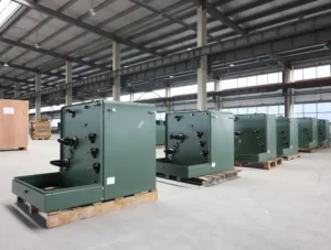
Pad-mounted Transformer
Dry-type Transformer
Oil immersed transformer
Table of Content
What are the types of grounding transformer?
According to the filling medium, the grounding transformer can be divided into oil type and dry type.
According to the number of phases, the grounding transformer can be divided into three-phase grounding transformer and single-phase grounding transformer.
Try for free information about the How to produce a distribution transformer ?
What is the purpose of grounding transformer?
The function of the grounding transformer is to provide an artificial neutral point for the system where the neutral point is not grounded, so that the grounding method of the arc suppression coil or small resistance can be used to reduce the capacitance current to the ground when the grounding short-circuit fault occurs in the distribution network, to improve the reliability of power supply of the power distribution system.
In China, 6kV, 10kV, and 35kV power grids in the power system, the neutral point is generally not grounded. The low-voltage side of the main transformer in the power grid is generally connected in a delta, and there is no neutral point that can be grounded. When a single-phase grounding fault occurs in the neutral point ungrounded system, the line voltage triangle still maintains symmetry, the power system can continue to supply power to users for 1 to 2 hours, and the capacitor current is relatively small (less than 10A), which will not cause intermittent arcs, some Instantaneous ground faults can disappear on their own, which is very effective in improving power supply reliability and reducing power outages. But with the continuous expansion of the urban power grid and the continuous increase of the cable outlet, the capacitance current of the system to the ground increases sharply, and the capacitance current flowing through the fault point after the single-phase grounding is large (more than 10A).
The arc is not easy to be extinguished, and it is easy to excite ferromagnetic resonance overvoltage and generate intermittent arc grounding overvoltage, which may cause insulation damage, trip the line, and expand the accident.
Let’s know learn more about the EAF TRANSFORMER MEXICO
Specifically:
The intermittent extinguishing and re-ignition of the single-phase grounding arc will generate arc grounding overvoltage, the amplitude of which can reach 4U (U is the normal phase voltage peak value) or higher, and the duration is long, which will cause extreme damage to the insulation of electrical equipment. It is a big hazard, forming a breakdown at the weak insulation; causing heavy losses.
Due to the dissociation of the air caused by the continuous arc, the insulation of the surrounding air is destroyed, and the phase-to-phase short circuit is prone to occur.
The ferromagnetic resonance overvoltage is generated, which is easy to burn out the voltage transformer and cause the damage of the arrester and may even cause the arrester to explode. These consequences will seriously threaten the insulation of power grid equipment and endanger the safe operation of the power grid.
In order to reduce the capacitance current to the ground when the single-phase ground fault occurs, it is necessary to install compensation devices such as arc suppression coils at the neutral point of the transformer. Small grounding short-circuit breaking current improves system power supply reliability.
Keep on reading Electrical transformer – DAELIM BELEFIC
Current status of grounding transformer application at home and abroad.
Chinese grounding transformer usually use Z-type wiring (or zigzag wiring). In order to save investment and substation space, a third winding is usually added to the grounding transformer to replace the transformer used to supply power to the equipment used in the substation. According to my country’s “Reactor” national standard, the grounding method of the grounding transformer can be divided into direct grounding; grounding through reactors, resistors and arc suppression coils. Direct grounding has not been used in our country, but the research department of electric power has begun to discuss this aspect. Foreign grounding transformers usually adopt or Z-type connection, which is used for 10kV ungrounded system, which constitutes the grounding protection of the distribution network.
The sequence current presents low impedance, making the grounding protection operate reliably
You may interested in Introduction of a special transformer – furnace transformer
Three-phase grounding transformer
This type of transformer adopts Z-type wiring (or zigzag wiring).
The difference from ordinary transformers is that each phase coil is divided into two groups and wound on the magnetic column of the phase in reverse.
The benefit of this connection is zero. The sequence magnetic flux can flow along the magnetic column, while the zero-sequence magnetic flux of the ordinary transformer flows along the leakage magnetic circuit, so the zero-sequence impedance of the Z-type grounding transformer is very small (about 10Ω), while the ordinary transformer is much larger. According to the regulations, when using an ordinary transformer with an arc suppression coil, its capacity shall not exceed 20% of the transformer capacity. Z-type transformers can be equipped with arc suppression coils of 90% to 100% capacity.
In addition to arc suppression coils, grounding transformers can also carry secondary loads, which can replace station transformers, thereby saving investment costs.
Single-phase grounding transformer
Single-phase grounding transformers Single-phase grounding transformers are mainly used for generators with neutral points and neutral point grounding resistance cabinets of Satons transformers to reduce the cost and volume of the resistance cabinets.
Working characteristics of grounding transformer
(1) The zero-sequence impedance is low to ensure the output of zero-sequence current;
(2) High excitation impedance to reduce no-load current;
(3) Low no-load loss to save energy consumption in daily operation.
Know more about The most complete explanation of grounding transformer
What is the grounding method of grounding transformer?
YNyn connection
The transformer with this connection method generally adopts a three-phase three-column iron core, and the neutral point of the high-voltage side can be connected to the arc suppression coil to achieve grounding. However, when the single-phase grounded zero-sequence current flows through the high-voltage side winding, the generated zero-sequence magnetic potential cannot be balanced by the secondary magnetic potential, and the zero-sequence magnetic flux in the same direction cannot form a loop in the three-column core. , so that a large amount of zero-sequence magnetic flux can only pass through the clip, the oil and the tank body to form a closed loop, thereby causing additional losses in the oil tank and clip, resulting in local overheating and limiting the utilization of transformer capacity. The relevant operating regulations of my country’s power sector have made the following provisions on the working state of the neutral point connection arc suppression coil of the YNyn connection transformer:
(1) The capacity of the arc suppression coil shall not exceed 20% of the rated capacity of the transformer;
(2) The zero-sequence voltage drop in the transformer generated by the zero-sequence current flowing through the arc suppression coil shall not exceed 10% of the rated phase voltage;
(3) The total three-phase zero-sequence current flowing through the arc suppression coil is not greater than 60% of the rated phase current of the transformer. The above regulations are mainly determined according to the maximum temperature limit that the local overheating caused by the zero-sequence magnetic flux will not exceed the hot spot of the transformer winding.
It can be seen from the above that the capacity of the grounding transformer connected by YNyn is far from being utilized, and its zero-sequence reactance value is also relatively large.
Try for free High voltage transformer – 138kv power transformer
YNd connection
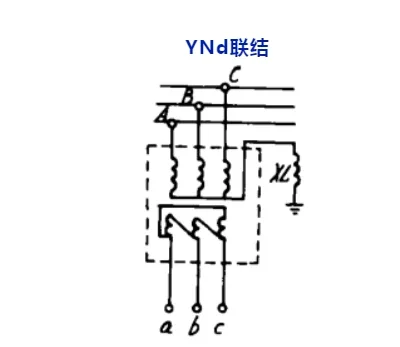
The YNd connection transformer is connected with the arc suppression coil XL. The characteristic of this connection method is that the delta connection on the secondary side can provide a closed path for the zero-sequence current, so the zero-sequence reactance is small. In addition, since the zero-sequence magnetic potentials of the primary and secondary windings on each core are balanced, the zero-sequence magnetic flux leakage is also small. However, when the YN connecting winding is outside, the additional loss of zero sequence caused in the fuel tank and other components cannot be completely avoided. When it is connected to the arc suppression coil, the utilization of its capacity will still be limited. Foreign experimental studies have shown that after considering additional losses, local overheating, insulation life and the limitation of the maximum temperature of the winding hot spot, the allowable working mode of the YNd-connected grounding transformer is:
(1) When the secondary full load is usually performed, the capacity of the arc suppression coil connected to the YN side shall not exceed 50% of the rated capacity of the transformer;
(2) When the secondary load is only 50% of the transformer capacity at ordinary times, the capacity of the arc suppression coil can be equal to the rated capacity of the transformer.
Although the secondary side of this connection can supply power to local loads or substations, its application will be greatly limited because it is difficult to supply power to mixed users of power and lighting at the same time due to the delta connection.
YN, opening d connection is connected with arc suppression coil XL. Similar to YNd connection is YN, opening d connection. A resistor or reactor can be connected to the side of the open triangle to adjust the zero-sequence reactance of the transformer. The resistors also dampen the ferromagnetic resonance of the network. If the three-phase five-column iron core is used, the zero-sequence impedance value can be greatly increased, and it is even possible to save an arc suppression coil, but the structure is complicated and the cost increases. In addition, the secondary use of open triangle junction can not meet the needs of power supply to regional loads and self-consumption, so this method is not used much.
Read my article on Know More About The Main Transformer – DAELIM
ZNyn connection
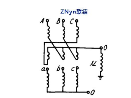
The ZN,yn connection transformer is connected with the arc suppression coil XL. This connection method is a common connection method for grounding transformers. Because of the zigzag connection method, the zero-sequence magnetic potentials in the upper and lower half windings on the same iron core column are exactly equal in size and opposite in direction. And they cancel each other out, so that the zero-sequence leakage flux is reduced to a very small value, so that its zero-sequence reactance value is very small, and its capacity can be equal to the capacity of the connected arc suppression coil.
The grounding transformer widely used at home and abroad is mainly this connection method. Because the low-voltage side adopts the yn junction method, it can simultaneously supply the local electricity or the self-use electricity of the substation. The capacity of the low pressure side is often smaller than that of the high pressure side. In most cases, the capacity of the low pressure side is in the range of 80-200kVA.
Although the rated capacity of the high-voltage side can be equal to the capacity of the connected arc suppression coil, the Z connection method will have 1.15 times more turns than the Y connection method, so the actual capacity of the grounding transformer should be 1.15 times the capacity of the arc suppression coil.
Try for free information about the The Ultimate Guide to Liquid Filled Transformer
What is the working principle of grounding transformer?
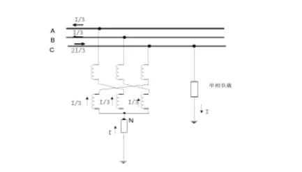
The working principle diagram of the grounding transformer when a single-phase fault occurs in the system is illustrated by the commonly used ZNyn wiring. During the operation of the grounding transformer, when a certain magnitude of zero-sequence current flows, the current flowing through the two single-phase windings on the same core column The directions are opposite and the magnitudes are the same, so that the magnetic potentials generated by the zero-sequence current are counteracted in the opposite direction, so that the zero-sequence impedance is also small.
So that when the grounding transformer fails, the neutral point can flow through the compensation current. Due to the small zero-sequence impedance, when the zero-sequence current passes through, the impedance voltage drop should be as small as possible to ensure the safety of the system. Because the grounding transformer has the characteristics of low zero-sequence impedance, when a single-phase grounding fault occurs in the C-phase, the grounding current I of the C-phase flows into the neutral point through the ground, and is divided into three equal parts and flows into the grounding transformer. The three-phase currents of the transformer are equal, so the displacement of the neutral point N remains unchanged, and the three-phase line voltage remains symmetrical.
However, in the manufacturing process, the number of turns and geometric dimensions of the upper and lower wraps of the high-voltage winding cannot be completely equal, so that the magnetic potential generated by the zero-sequence current cannot be counteracted exactly, and a certain zero-sequence impedance is still generated, usually around 6-10Ω. , Compared with the zero-sequence impedance of the star-connected transformer of 600Ω, its advantages are self-evident. In addition, meandering grounded transformers keep no-load current and no-load losses as small as possible. Compared with ordinary star-connected transformers, since each phase iron core of zigzag-connected transformers is composed of windings of two iron core columns, combined with its vector diagram, it can be seen that compared with ordinary star-connected transformers, when the voltage is the same, it needs to be wound 1.16 times more. . Under the neutral point resistance grounding method, when the urban distribution network is single-phase grounded, the amplitudes of the zero-sequence impedance and the positive-sequence impedance are very different. When three-phase positive and negative sequence currents flow, the magnetic potential on each core leg of the grounding transformer is the phasor sum of the magnetic potentials of the two windings belonging to different phases on the core leg. The magnetic potential on the three iron core columns is a set of three-phase balance quantities with a phase difference of 120°. The generated magnetic flux can form a loop with each other on the three iron core columns. The magnetic circuit reluctance is small, the magnetic flux is large, and the induced potential is large. , showing a large positive sequence and negative sequence impedance; therefore, the grounding transformer has the characteristics of large positive and negative sequence impedance and small zero sequence impedance.
Let’s know learn more about the NEW ZEALAND CUSTOMERS
What is the technical specification of grounding transformer?
In order to meet the needs of arc suppression coil grounding compensation in the distribution network, and also to meet the needs of power and lighting loads in substations, the main parameters of the grounding transformer need to be reasonably set for the selection of transformers connected by Z-type wiring.
(1) The capacity of the primary side of the rated capacity grounding transformer is matched with the capacity of the arc suppression coil. According to the capacity specification of the existing arc suppression coil, it is recommended to set the capacity of the grounding transformer to 1.05-1.15 times the capacity of the arc suppression coil. For example, the capacity of the grounding transformer for a 200kVA arc suppression coil is 215kVA.
(2) The total current flowing through the neutral point of the transformer when the neutral point compensation current is single-phase fault:
picture
In the above formula:
U is the distribution network line voltage (V); Zx is the impedance of the arc suppression coil (Ω);
Zd is the primary zero-sequence impedance of the grounding transformer (Ω/phase);
Zs is the system impedance (Ω);
The duration of the neutral point compensation current should be the same as the continuous working time of the arc suppression coil, which is 2 hours as specified.
(3) Zero-sequence impedance Zero-sequence impedance is an important parameter of the grounding transformer, which has an important influence on the relay protection limiting single-phase grounding short-circuit current and suppressing overvoltage. For zigzag (Z-type) and star/open delta connected grounding transformers without secondary coils, there is only one impedance, that is, zero-sequence impedance, so that the manufacturing department can meet the requirements of the power department.
(4) Loss loss is an important performance parameter of grounding transformer. For grounding transformer with secondary coil, its no-load loss can be the same as that of double-winding transformer of the same capacity. For the load loss, when the secondary side is running at full load, due to the light load on the primary side, the load loss is smaller than the load loss of a dual-winding transformer with the same capacity as the secondary side.
(5) According to the national standard, the temperature rise of the grounding transformer has the following provisions:
1) The temperature rise under the rated continuous current should comply with the provisions of the national standard for dry-type transformers of general power transformers, but it is mainly suitable for grounding transformers with frequent loads on the secondary side;
2) When the duration of the short-time load current is less than 10s (this situation mainly occurs when the neutral point is connected to the resistance), the temperature rise should meet the requirements of the national standard power transformer for the temperature rise limit under short-circuit conditions ;
3) The temperature rise of the grounding transformer and the arc suppression coil should comply with the regulations on the temperature rise of the arc suppression coil: for the winding temperature that continuously flows through the rated current of 80K, it is mainly suitable for the grounding transformer with star/open delta connection; For a winding whose maximum flow time of rated current is specified as 2h, the specified temperature is 100K.
This situation complies with the working conditions of most grounding transformers; for a winding whose maximum circulation time is specified at 30min, the specified temperature is 120K. The starting point of the above regulations is based on the fact that the maximum temperature of the winding hot spot does not exceed 140 ° C ~ 160 ° C under the most severe conditions, in order to ensure the safe operation of the insulation and not seriously endanger the insulation life.
Keep on reading 110 kv Oil Filled Power Transformer – DAELIM BELEFIC
DAELIM GROUNDING TRANSFOMMER Transformer Specification reference:
Parameter | Value |
Identification | Zig-Zag Grounding Transfomer |
Cooling Class | Oil Natural – Air Na tural (ONAN) |
Temperature Rise (windings average and top oil when energized continuously at 46kV) | 65°C
|
High Voltage / Primary Voltage | 46000V |
Basic Insulation Level | 250kV |
Winding Connection | Zig – Zag |
Phases | 3 |
Frequency | 60Hz |
Maximum Fault Current | 3000 A for 10 seconds |
Continuous Neutral Current | 90A |
Continuous Phase Current | 30A |
Current Transformers | Phase A: 2x 1200:5 MR CT C400 Phase B: 2x 1200:5 MR CT C400 Phase C:2x 1200:5 MR CT C400 Neutral: 2 x 1200:5 MR CT C400 |
Zero Sequence Impedance | 10 Ohms/Phase (current nameplate value is not applicable) |
Winding | Copper |
Core | Cold Rolled Grain-Oriented The core and coil assembly shall be designed and manufactured to meet the short-circuit requirements of IEEE C57.12.90 |
Cooling System
| Tank Surface (fat cooling panels if needed) Shut-off Valves on Top and Bottom |
Dielectric fluid preservation system
| Sealed tank Nitrogen pressurized |
Tank pressures
| Maximum positive pressure: 10 PSI Maximum negative pressure: 14.7 PSI |
Valves
| – Mounted on flanges with machine-grooved retainers for gasketing 2-inch Globe Drain with 3/8 inch Sampler 1-inch Globe Top Filter Press 2-inch NPT Vacuum 1-inch Fill/Vent Provision 2″ Gate Type for Dissolved Gas Monitor (DGM) Port (future) |
Dielectric Fluid | flame-retardant, biodegadable and ambient friendly (ASTM D6871) |
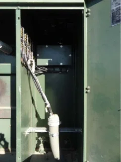
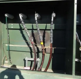
Bushings(see Photographs I1 to 13 in Table 2) | Condenser type Location and termination: to match existing |
Accessories
| CT Terminal blocks to match existing transformer Dial Type Liquid Temperature Gauge with (2) Alam Contacts (wired to terminal block) .Magnctic Liquid Level Gauge with Alarm Contact (wired to terminal block) Pressure-Vacuum Gauge with Alarm (sce Drawing 9856-D-914 and Photographs in Contacts (wired to terminal block) – Pressure-Vacuum Bleeder Device – Winding Temperature Gauge with (4) Alarm Contacts (wired to terminal block) . Mechanical Pressure Relief Device with Alarm Contact (wired to terminal block) – Rapid Pressure Rise Rely with Alarm Contact (wired to terminal block) |
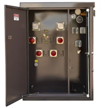
Cabinet | NEMA 3R Sections 1: Power Section 2: Control Painted same color as main tank |